


122 MFP unit explanation ENWW
13SCANFAN_CONT-18 (PRCB to
SCDB)
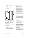
FM9 (scanner cooling) ON/OFF
control signal
[L]: FM9 on
[H]: FM9 off
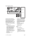
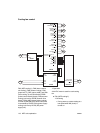
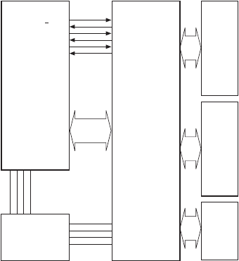
Control panel control
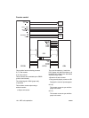
The control panel consists of OB1 (operation
board 1), PAKB (panel key board), and LCD
(indicator board). The LCD has a backlight
which is driven by OB IVNB (OB inverter)
and touch switches which correspond to the
display messages.
The control panel is controlled by the OB1
based on the serial data output from the ICB
(image control board).
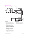
1 Operation
a LED ON operation
The LED on the OB1 (operation
board/1) is controlled by sub CPU of
OB1 at the command of ICB (image
control board).
b LCD (indicator board) control
1 LCD (indicator board) display
operation
The LCD (image control board)
displays various information
according to the 4-bit parallel data
from ICB (image control board) via
OB1 (operation board 1).
2 Backlight ON operation
The LCD (indicator board) has a
backlight (cold cathode tube) to
facilitate viewing. The backlight is
driven by OB INVB (OB inverter), and
controlled by the OB1 (operation
board/1).
3 PAKB (panel key board) control
The LCD (indicator board) has PAKB
(panel key board) to allow you to
select an item displayed on the LCD
directly. PAKB is controlled by OB1
(operation board/1).
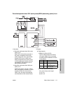
2 Signals
a Input signals
1 S_IN2 (OB1 to ICB)
Serial data which informs ICB (image
control board) of the operation state
of OB1 (operation board/1).
2 /CTS2 (OB1 to ICB)
Signal which indicates that data can
be sent from OB1 (operation board/1)
to ICB (image control board)
When this signal is at the high level
([H]), ICB stops sending the S_OUT2
signal.
3 /DSR2 (OB1 to ICB)
Acknowledgment signal which is
returned each time OB1 (operation
board/1) receives one-byte data from
ICB (image control board)
OB1
LCD
PAKB
OB INVB
DCPS
ICB
24V1
5V2
S.GND
P.GND
S OUT2
S IN2
/RTS2
/CTS2
/DTR2
/DSR2