


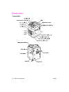
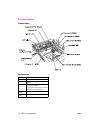
48 MFP unit explanation ENWW
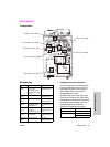
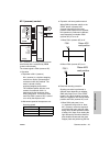
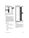
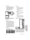
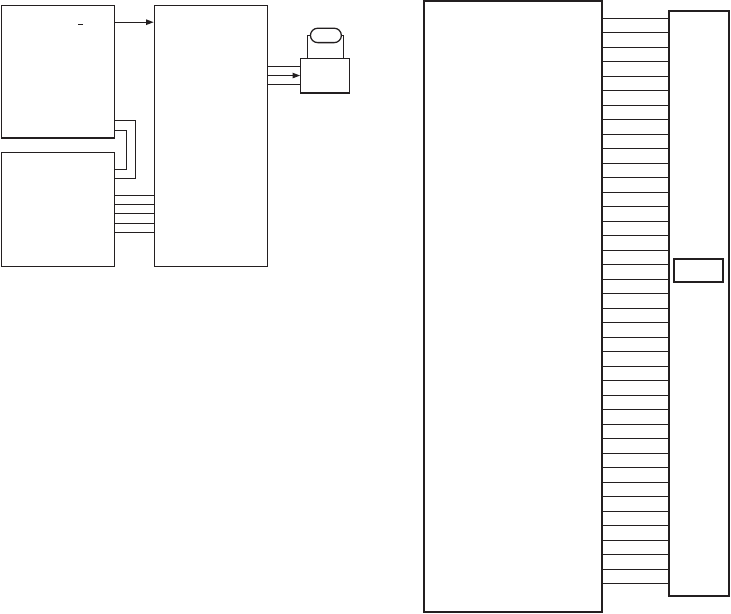
Exposure control
L1 (exposure lamp) is driven by L1 INVB (L1
inverter) and is controlled by PRCB (printer
control board) via SCDB (scanner drive
board).
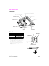
1 Operation
L1 (exposure lamp) is a xenon lamp driven
by the inverter circuit. The xenon lamp can
emit a constant light intensity and
generates less heat than other lamps, so it
does not require the light intensity control
circuit that has been used in the existing
machines, requiring no thermal protector
circuit. However, since L1 is held lit when
the exposure unit is stationary in the ADF
mode, FM9 (scanner cooling) is installed
in the read section.
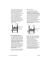
2 Signals
a Output signals
1 EXP_CONT (PRCB to SCDB)
L1 (exposure lamp) ON/OFF control
signal
[L]: L1 on
[H]: L1 off
2 CONT (SCDB to L1 INVB)
L1 (exposure lamp) ON/OFF control
signal
[L]: L1 on
[H]: L1 off
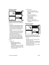
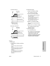
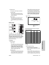
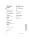
Original read control
Original read control is performed by ADB
(A/D converter board) and CCD sensor
installed in ADB.
1 Operation
The light reflected by the exposed original
is input to the CCD sensor through the
lens. The analog voltage corresponding to
the quantity of the input light is
A/D-converted in the ADB (A/D converter
board), being output to the ICB (image
control board).
L1 INVB
SCDB
24V
CONT
LAMP.PG
L1
PRCB
EXP CONT
DCPS
24V1
5V2
S.GND
P.GND
L.PG
5V2
S.GND
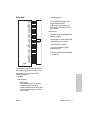
ICB
ADB
CCD
12V2
12V2
GND
APR
ADRST
PDWN
GND
TCK
/TCK
GND
RCK
/RCK
GND
LCLK1
/LCLK1
GND
SCLK
/SEN
SDI
SDO
TG
CLAMP
GND
BCLAMP
GND
D0
/D0
GND
D1
/D1
GND
D2
/D2
GND
LCLK0
/LCLK0
GND
5V2
5V2
GND