


ENWW Developing unit 69
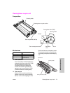
MFP unit explanation
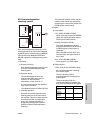
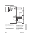
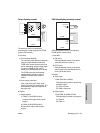
Toner density control
The density of toner is controlled by
controlling M12 (toner supply) from PRCB
(printer control board).
1 Operation
a Toner density detection
The reference patch density is detected
using the patch detection method of
TCSB (toner control sensor board) and
the corresponding analog voltage signal
is output to PRCB (printer control
board), thus detecting the toner density.
The PRCB compares the detected
voltage with the reference value to
determine whether toner must be
added.
b Toner supply operation
Upon read of the patch, M12 (toner
supply) is turned on to supply toner. The
time needed to add toner depends on
the paper size.
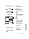
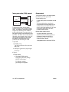
2 Signals
a Output signals
1 TNSM_A, AB (PRCB to M12)
A-phase drive signal of M12 (toner
supply)
2 TNSM_B, BB (PRCB to M12)
B-phase drive signal of M12 (toner
supply)
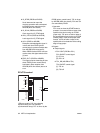
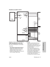
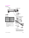
FM4 (developing suction) control
FM4 (developing suction) is controlled by
PRCB (printer control board).
1 Operation
a ON timing
FM4 (developing suction) is turned on
when M2 (drum) is turned on.
b OFF timing
FM4 (developing suction) is turned off
after a lapse of the specified time from
turning off of M2 (drum).
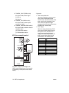
2 Signals
a Input signal
1 FM2 EM (FM4 to PRCB)
FM4 (developing suction) abnormality
detection signal
[L]: FM4 is normal.
[H]: FM4 is abnormal.
b Output signal
1 SUCTFAN_D (ACDB to FM4)
FM4 (developing suction) drive signal
[L]: FM4 off
[H]: FM4 on
M12
PRCB
TNSM24V
TNSM24V
TNSM A
TNSM AB
TNSM B
TNSM BB
DCPS
24V1
5V2
S.GND
P.GND
TCSB
12V
A.GND
DMLED CONT
DM MONI EX
DJLED CONT
DM SIG EX
DRUM JSIG EX
TNLED REF
TEMP
3.3V2
FM4
PRCB
SUCTFAN D
SFAN EM
P.GND
DCPS
24V1
5V2
S.GND
P.GND