


ENWW Scanner section 143
MFP disassembly/assembly
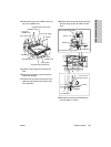
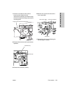
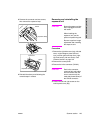
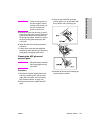
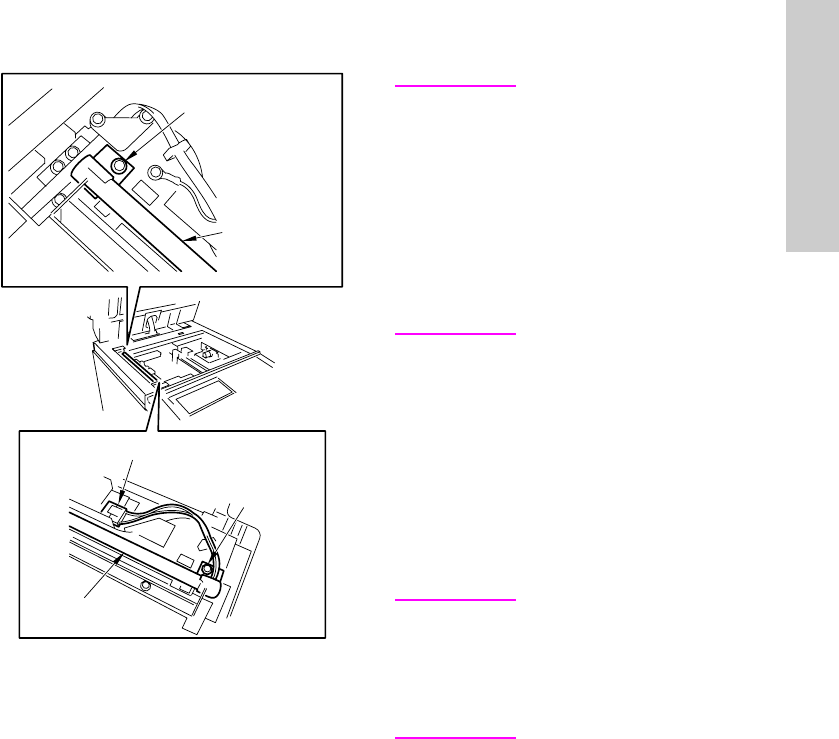
3 Remove the connector and two screws,
then remove the exposure lamp.
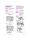
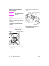
4 Reinstall the above parts following the
removal steps in reverse.
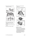
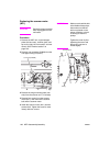
Removing and reinstalling the
exposure unit
CAUTION Be sure the power cord has
been unplugged from the
wall outlet.
When installing the
exposure unit, use the
optics unit positioning tool.
Be sure to perform image
adjustment after installing
the exposure unit.
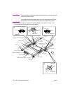
Procedure
1 Remove the right side cover (top), left side
cover, original stopper plates (left and
rear), scanner glass and top cover (right,
left, front center, and rear center). See
“External section” on page 132.
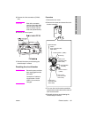
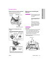
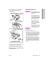
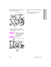
2 Remove the control panel.
3 Remove the inline connector (CN162).
CAUTION Each inline connector
consist of two male sides
and one female side. Be
sure to remove only the
male side (shown below) of
the CN162 connector.
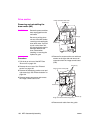
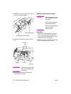
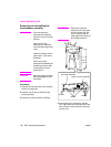
4 Loosen the left and right screws on the
control panel cover (top).
Screw
Screw
Exposure lamp
Exposure lamp
Connector