


ENWW Corona unit section 59
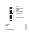
MFP unit explanation
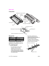
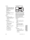
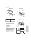
1 Operation
a Charging
A Scorotron charging method is used.
24 VDC supplied from DCPS is raised
to a negative DC voltage which is then
discharged after being applied to the
charging wire.
Charge output range:
-600 µA to -1200 µA
b Grid voltage
The grid voltage is output from HV to
the charging plate.
Grid voltage output range: -500 V to
-1000 V
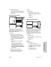
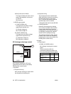
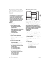
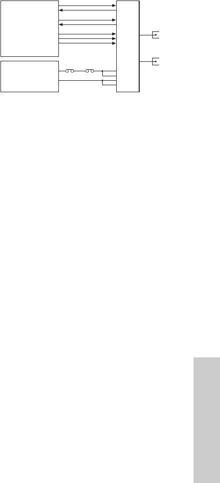
2 Signals
a Input signal
1 EM (C).SIG (HV to PRCB)
This signal indicates the leak or short
state of the charging corona unit.
[L]: Normal
[H]: Abnormal
b Output signals
1 C.CONT (PRCB to HV)
This signal turns on/off the charging
wire.
[L]: Charging voltage on
[H]: Charging voltage off
2 TXD (PRCB to HV)
Output level of each high voltage
electrode.
Serial data signal for control
3 CLK (PRCB to HV)
Clock signal for TXD
4 LATCH (PRCB to HV)
Latch signal for TXD
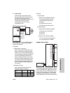
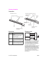
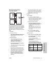
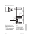
Transfer/separation control
The voltages applied to the transfer wire and
separation wire is supplied from HV (high
voltage unit) and are controlled by PRCB
(printer control board). The levels of outputs
to these wires are transmitted using 8-bit
serial data. This serial data includes the level
information for all outputs driven by HV,
excluding the ON/OFF control signal.
Accordingly, a separate signal line is
provided to turn on/off only the transfer wire
or separation wire.
1 Operation
a Transfer
Positive DC high voltage is used for
transfer.
Transfer DC output range: 50 µA to
600 µA
b Separation
AC high voltage and negative DC
voltage are used for separation.
Separation AC output range: 4kV to
5.7kV
Separation DC output range: 0 µA to
-400 µA
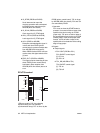
2 Signals
a Input signals
1 EM (T).SIG (HV to PRCB)
This signal indicates the leak or short
state of the transfer corona unit.
[L]: Normal
[H]: Abnormal
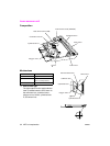
PRCB
DCPS
24V2
P.GND
TRANSFER
SEPARATION
MS1 MS2
HV
T.CONT
EM(T).SIG
S.CONT
EM(S).SIG
TXD
CLK
LATCH