User’s Manual
IBM PowerPC 750GX and 750GL RISC Microprocessor
PowerPC 750GX Overview
Page 42 of 377
gx_01.fm.(1.2)
March 27,2006
1.4 PowerPC Registers and Programming Model
The PowerPC Architecture defines register-to-register operations for most computational instructions. Source
operands for these instructions are accessed from the registers or are provided as immediate values
embedded in the instruction itself. The 3-register instruction format allows specification of a target register
distinct from the two source operands. Only load-and-store instructions transfer data between registers and
memory.
PowerPC processors have two levels of privilege: supervisor mode and user mode.The supervisor mode of
operation is typically used by the operating system. The user mode of operation, also called the problem
state, is typically used by the application software. The programming models incorporate 32 GPRs, 32 FPRs,
Special-Purpose Registers (SPRs), and several miscellaneous registers. Each PowerPC microprocessor
also has its own unique set of Hardware-Implementation-Dependent (HID) Registers.
While running in supervisor mode, the operating system is able to execute all instructions and access all
registers defined in the PowerPC Architecture. In this mode, the operating system establishes all address
translations and protection mechanisms, loads all Processor State Registers, and sets up all other control
mechanisms defined in the PowerPC 750GX processor. While running in user mode (problem state), many of
these registers and facilities are not accessible, and any attempt to read or write these register results in a
program exception.
Figure 2-1, PowerPC 750GX Microprocessor Programming Model—Registers, on page 58 shows all the
750GX registers available at the user and supervisor levels. The numbers to the right of the SPRs indicate
the number that is used in the syntax of the instruction operands to access the register. For more information,
see Chapter 2, Programming Model, on page 57.
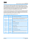
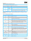
The following tables summarize the PowerPC registers implemented in 750GX, and describe registers
(excluding SPRs) defined by the architecture.
Table 1-1. Architecture-Defined Registers (Excluding SPRs)
Register Level Function
CR User
The Condition Register (CR) consists of eight 4-bit fields that reflect the results of certain opera-
tions, such as move, integer and floating-point compare, arithmetic, and logical instructions. The
register provides a mechanism for testing and branching.
FPRs User
The 32 Floating Point Registers (FPRs) serve as the data source or destination for floating-point
instructions. These 64-bit registers can hold single-precision or double-precision floating-point val-
ues.
FPSCR User
The Floating-Point Status and Control Register (FPSCR) contains the floating-point exception sig-
nal bits, exception summary bits, exception enable bits, and rounding control bits needed for com-
pliance with the IEEE 754-1985 standard.
GPRs User
The 32 GPRs contain the address and data arguments addressed from source or destination fields
in integer instructions. Also, floating-point load-and-store instructions use GPRs to address mem-
ory.
MSR Supervisor
The Machine State Register (MSR) defines the processor state. Its contents are saved when an
exception is taken and restored when exception handling completes. The 750GX implements
MSR[POW], defined by the architecture as optional, which is used to enable the power manage-
ment feature. The 750GX-specific MSR[PM] bit is used to mark a process for the performance
monitor.
SR0–SR15 Supervisor
The sixteen 32-bit Segment Registers (SRs) define the 4-GB space as sixteen 256-MB seg-
ments.The 750GX implements Segment Registers as two arrays—a main array for data accesses
and a shadow array for instruction accesses (see Figure 1-1 on page 25). Loading a segment entry
with the Move-to Segment Register (mtsr) instruction loads both arrays. The mfsr instruction
reads the master register, shown as part of the data MMU in Figure 1-1 on page 25.


