


IBM 3494 Tape Libraries
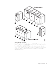
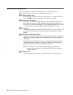
Figure 1 on page 3 shows three possible configurations of the 3494. The 3494 is
available in multiple configurations using one control unit frame and up to fifteen
optional frames. The available frame types are:
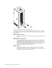
v The tape library control unit frame, 1 or 3, includes the operator panel, a
tape subsystem (3490E Model CxA or F1A with drives, 3590 Model B1A tape
drives, or 3590 Model A00 or A50 Control Unit with drives), a library manager,
cartridge storage cells, a cartridge accessor, and if ordered, the Convenience
Input⁄Output Station. One control unit frame is required in every library
configuration.
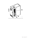
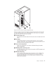
v The optional drive unit frame 4 contains additional cartridge storage and may
contain a 3490E Model CxA or F1A tape subsystem, 3590 Model B1A tape
drives, or a 3590 Model A00 or A50 Control Unit with drives.
v The optional Model B16 Virtual Tape Server (VTS) frame 5 contains additional
cartridge storage and the controller and associated disk storage for the VTS. A
drive unit frame4 that holds the 3590 Model B1A tape drives, managed by the
Model B16 VTS, must be located to the left of the Model B16 Virtual Tape Server
frame.
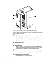
v The optional stand-alone 3494 Model B18 Virtual Tape Server frame 8 contains
the controller and associated disk storage for the VTS. A drive unit frame 4 that
holds the 3590 Model B1A tape drives, managed by the Model B18 VTS, may be
located at any position in the library (except frame 1) but must be within a
distance of 14 m (46 ft.) from the Model B18.
v The optional frame 6 contains additional cartridge storage only.
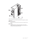
v The Optional HA1 Service Bays (left 2 and right 7) contain a service area for
the accessors.
2 Magstar 3494 Tape Library Operator Guide