


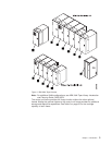
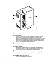
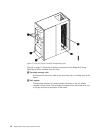
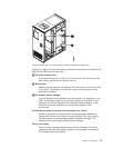
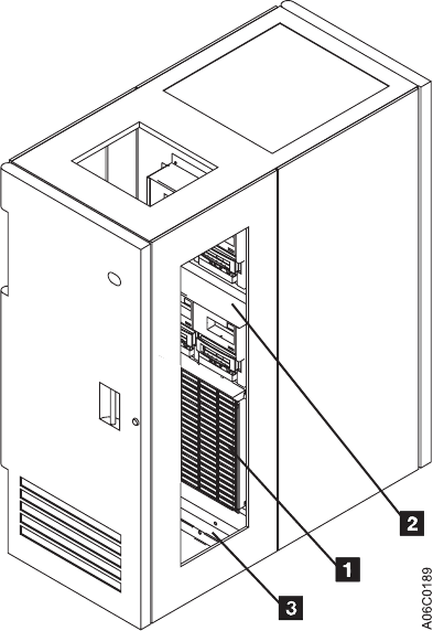
Figure 7 on page 10 shows the functional components of the drive unit frame with
four 3590 tape subsystems and a 3590 Model A00 or A50 Control Unit, viewable
from the rear (shown with rear door removed):
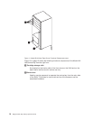
1 Cartridge storage cells
Are located on the interior side of the front door and on the back wall of the
frame.
2 Rail system
The cartridge accessor is carried through the library on the rail system
installed in each frame. The rail system consists of two horizontal rails, one
at the top and one at the bottom of the frame.
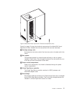
3 Power control compartment
Power to all components in the frame is distributed through the power
control compartment.
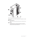
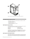
4 3590 Model A00 or A50 Control Unit
The 3590 Model A00 or A50 Control Unit consists of a RISC processor and
associated adapter cards.
5 3590 tape subsystems
From one to four 3590 magnetic tape subsystems can be installed along
with the 3590 Model A00 or A50 Control Unit. From one to six 3590
magnetic tape subsystems can be installed without a Model A00 or A50
Control Unit (not shown).
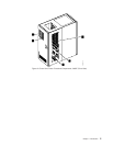
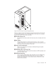
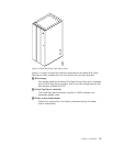
Figure 6. Drive Unit Frame Functional Components (front)
Chapter 1. Introduction 9