


Inserting Cartridges
Cartridges can be inserted into the library in the following ways:
v See “Initial Cartridge Installation” on page 58.
v See “Using Empty Cartridge Cells to Insert Cartridges”.
v See “Using the Convenience Input⁄Output Station Feature to Insert Cartridges” on
page 78.
v See “Using the High-Capacity Input/Output Facility” on page 81.
Note: The type of input⁄output facility available to the operator was defined during
the teach process.
Note: Make sure that there are enough available cells for the cartridges you are
inserting. Use the Operational status panel (Figure 61 on page 111) to check
the number of empty storage cells in the library.
Inserting stacked volumes for a Virtual Tape Server (VTS) requires that 1 or more
volser ranges have been set up for the VTS before the stacked volumes are
inserted. Refer to Figure 94 on page 162.
Inserting logical volumes for a VTS is accomplished using the “Insert Logical
Volumes” panel. Refer to Figure 95 on page 164.
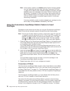
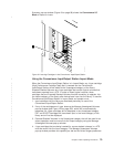
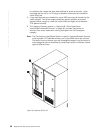
Using Empty Cartridge Cells to Insert Cartridges
Attention: Never place Exported Stacked Volumes into free cells, as this will cause
the data on them to be overwritten.
1. Place the library in Pause mode by pressing the Pause mode Motion Control
switch on the operator panel.
2. When the Pause mode status light is lit, unlock and open the front door on any
frame.
3. Insert the cartridges into any empty cartridge storage cells, except error
recovery cell locations 1 A 1 (1 A 3 instead of 1 A 1 if the optional Dual Gripper
feature is installed), 1 A 20, 1 A 19 (if two service volumes are used) and the
high-capacity output facility cells. See “Cartridge Placement” on page 59 for
cartridge placement guidelines.
Note: The error recovery cell locations for a High Availability, single gripper unit
are 1 A 1 and 1 A 2. The error recovery cell locations for a High
Availability, dual gripper unit are 1 A 3 and 1 A 4. On all High Availability
models, service volumes are stored in the service bays.
Note: If there is no convenience I/O station and no High Capacity I/O defined,
then cell 2 A 1 is reserved for ejects.
Note: The cartridges must be inserted into the cartridge storage cells so that
the leader block is on the right and the volser label is visible. See
Figure 16 on page 20.
4. Close and lock the front door.
5. Press the Auto mode Motion Control switch on the operator panel.
Chapter 5. Basic Operating Procedures 77
|
|