REAL ADDRESS MODE
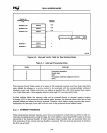
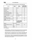
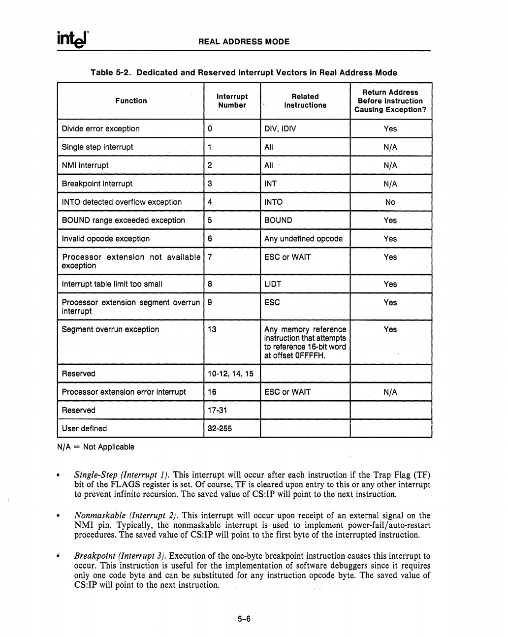
Table 5-2. Dedicated and Reserved
Interrupt
Vectors
in Real Address Mode
Interrupt Related
Return Address
Function
Before
Instruction
Number Instructions
Causing Exception?
Divide error exception
0 DIV,IDIV
Yes
Single step interrupt 1 All
N/A
NMI interrupt 2 All
N/A
Breakpoint interrupt 3
INT
N/A
INTO detected overflow exception 4
INTO No
BOUND range exceeded exception
5 BOUND Yes
Invalid opcode exception
6
Any undefined opcode
Yes
Processor
extension
not
available 7
ESC
or WAIT
Yes
exception
Interrupt table limit too small
8 LlDT Yes
Processor extension segment overrun
9
ESC
Yes
interrupt
Segment overrun exception 13 Any memory reference
Yes
instruction that attempts
to reference 16-bit word
at offset
OFFFFH.
Reserved
10-12,14,15
Processor extension error interrupt 16
ESC
or WAIT
N/A
Reserved 17-31
I User defined
132-255
N/A
= Not Applicable
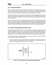
Single-Step (Interrupt 1). This interrupt will occur after each instruction if the Trap Flag (TF)
bit of the FLAGS register
is
set. Of course,
TF
is
cleared upon entry
to
this or any other interrupt
to prevent infinite recursion. The saved value of
CS:IP
will
point to the next instruction.
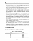
Nonmaskable (Interrupt
2).
This interrupt will occur upon receipt of an external signal
on
the
NMI
pin. Typically, the nonmaskable interrupt
is
used to implement power-failJauto-restart
procedures. The saved value of
CS:IP will.point to the first byte of the interrupted instruction.
Breakpoint (Interrupt
3).
Execution of the one-byte breakpoint instruction causes this interrupt
to
occur. This instruction
is
useful for the implementation of software debuggers since it requires
only one code byte and can be substituted for any instruction opcode byte. The saved value of
CS:IP
will
point to the next instruction.
5-6


