TABLE OF CONTENTS
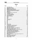
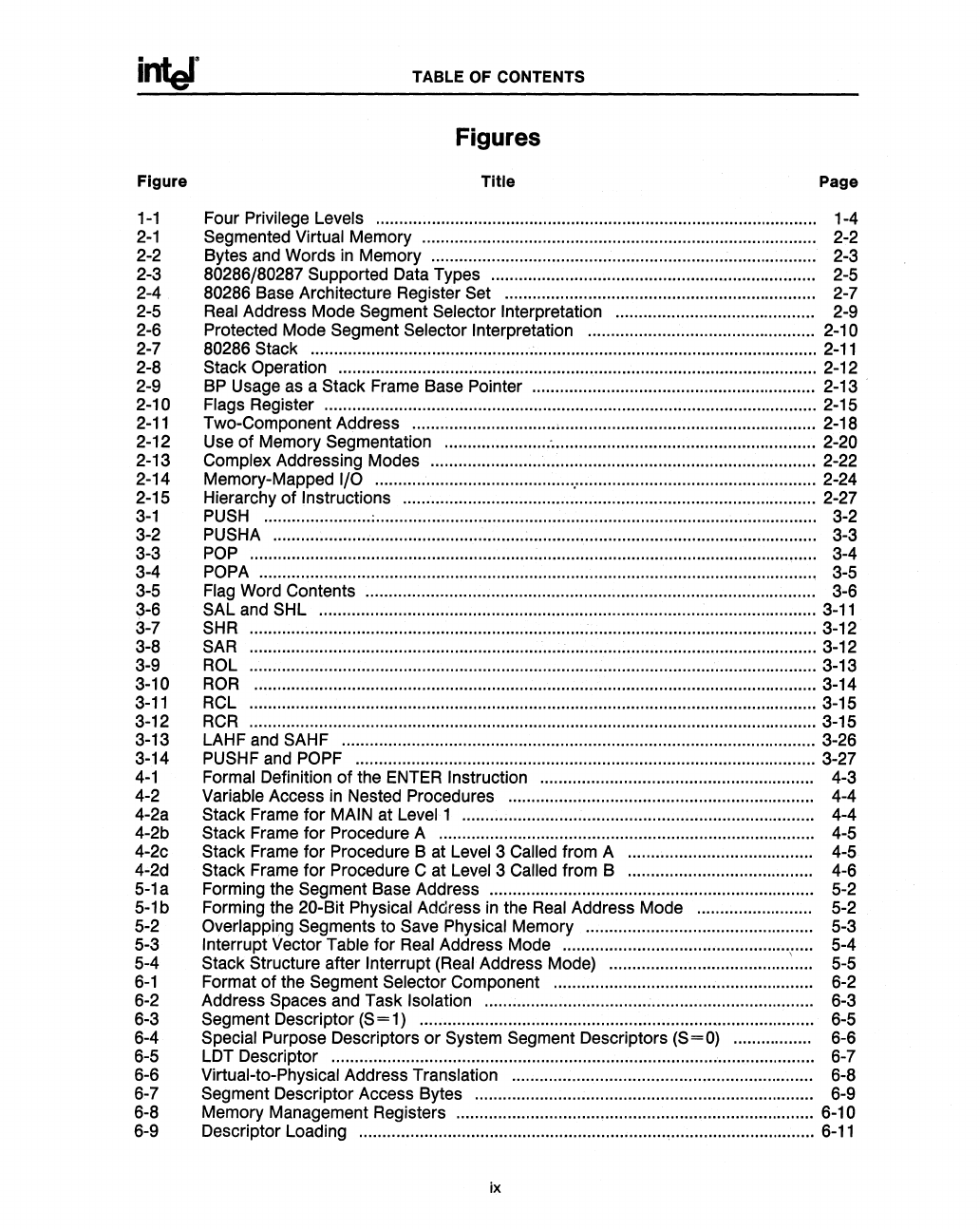
Figures
Figure Title Page
1-1
Four Privilege Levels .......
.....
........... ...... ........ ..........
....
..........
....
.......... .................... 1-4
2-1
Segmented Virtual Memory
...
................. ...................... ................. ........... ......... ...... 2-2
2-2 Bytes
and
Words
in
Memory...................................................................................
2-3
2-3 80286/80287 Supported
Data
Types .......... .................. .............. .......... ........ .......... 2-5
2-4 80286 Base Architecture Register
Set
................................................................... 2-7
2-5
Real
Address Mode Segment Selector Interpretation ........................................... 2-9
2-6 Protected Mode Segment
Selector Interpretation ................................................. 2-10
2-7 80286
Stack .............................................................................................................
2-11
2-8 Stack Operation ....................................................................................................... 2-12
2-9
BP
Usage
as
a Stack Frame Base Pointer ............................................................. 2-13
2-10
Flags Register .......................................................................................................... 2-15
2-11
Two-Component Address ....................................................................................... 2-18
2-12 Use of Memory Segmentation ...................... : ......................................................... 2-20
2-13
Complex Addressing Modes ................................................................................... 2-22
2-14 Memory-Mapped
I/O ................................................................................................ 2-24
2-15 Hierarchy of
Instructions ......................................................................................... 2-27
3-1
PUSH
....................... :............................................................................................... 3-2
3-2 PUSHA...................................................... .................... ........................ ................... 3-3
3-3
POP
.......................................................................................................................... 3-4
3-4
POPA
........................................................................................................................ 3-5
3-5
Flag
Word Contents .................................. .......................................
.....
................... 3-6
3-6
SAL
and
SHL ...........................................................................................................
3-11
3-7
SHR
.......................................................................................................................... 3-12
3-8
SAR
.......................................................................................................................... 3-12
3-9
ROL
.......................................................................................................................... 3-13
3-10
ROR
......................................................................................................................... 3-14
3-11
RCL
.......................................................................................................................... 3-15
3-12
RCR
.......................................................................................................................... 3-15
3-13 LAHF
and
SAHF
...................................................................................................... 3-26
3-14
PUSHF
and
POPF
................................................................................................... 3-27
4-1
Formal Definition of the
ENTER
Instruction ........................................................... 4-3
4-2
Variable Access
in
Nested Procedures .................................................................. 4-4
4-2a
Stack Frame for
MAIN
at
Level
1 ............................................................................ 4-4
4-2b
Stack Frame for Procedure A ........ ...... ...... ................. .................. .......... ................ 4-5
4-2c
Stack
Frame
for Procedure B
at
Level
3
Called
from A ....... :................................ 4-5
4-2d
Stack
Frame
for Procedure C at
Level
3 Called from B ........................................ 4-6
5-1
a Forming the Segment Base Address
....
........ .............. .......... .............. ....................
5-2
5-1
b Forming
the
20-Bit Physical Address
in
the
Real
Address Mode
....
........... .......... 5-2
5-2
Overlapping Segments to
Save
Physical Memory ...... .................. ...... ................... 5-3
5-3
Interrupt Vector Table for
Real
Address Mode ...................................................... 5-4
5-4
Stack Structure after Interrupt
(Real
Address Mode) ....................................... :.... 5-5
6-1
Format of the Segment Selector Component ........................................................
6-2
6-2
Address Spaces
and
Task Isolation ....................................................................... 6-3
6-3
Segment Descriptor
(S
=
1)
............ ............ ...... .......... .................. .......... .................
6-5
6-4
Special Purpose Descriptors
or
System Segment Descriptors (S=O) .................
6-6
6-5 LDT Descriptor ........................................................................................................
6-7
6-6
Virtual-to-Physical Address Translation ...... ...... .......... .............. ............ .................
6-8
6-7
Segment Descriptor Access Bytes .........................................................................
6-9
6-8
Memory Management Registers ............................................................................. 6-10
6-9
Descriptor Loading ..................................................................................................
6-11
ix


