APPENDIX A
MACHINE INSTRUCTION ENCODING
AND
DECODING
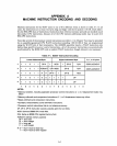
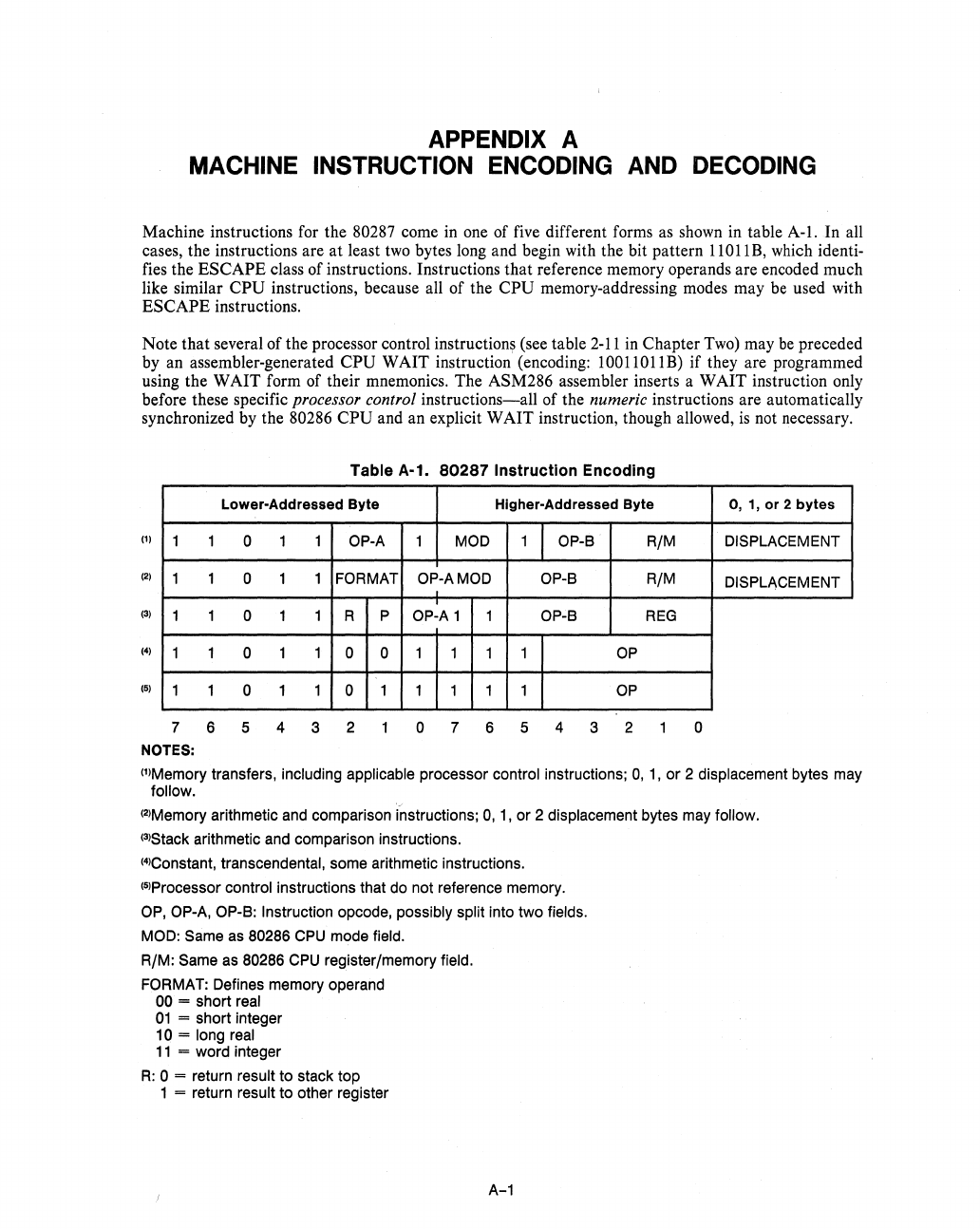
Machine instructions for the 80287 come
in
one of five different forms as shown in table A-I.
In
all
cases, the instructions are
at
least
two
bytes long and begin with the bit pattern 11011B, which identi-
fies the ESCAPE class of instructions. Instructions that reference memory operands are encoded much
like similar
CPU instructions, because all of the CPU memory-addressing modes may
be
used with
ESCAPE instructions.
Note that several of the processor control
instruction~
(see table
2-11
in
Chapter
Two)
may
be
preceded
by an assembler-generated
CPU WAIT instruction (encoding: 10011011B) if they are programmed
using the WAIT form of their mnemonics. The ASM286 assembler inserts a WAIT instruction only
before these specific
processor control instructions-all of the numeric instructions are automatically
synchronized
by
the 80286 CPU and an explicit WAIT instruction, though allowed,
is
not necessary.
Table
A-1.
80287
Instruction
Encoding
Lower-Addressed Byte
(1)
1
1
0 1
1
OP-A
(2)
1 1
0 1
1
FORMAT
(3)
1 1 0 1 1 R P
(4)
1 1 0 1 1 0 0
(5)
1
1
0 1 1 0
1
7 6 5 4 3 2
NOTES:
Higher-Addressed Byte
1
MOD
1 OP-S
R/M
OP-AMOD OP-S
R/M
OP-A 1 1
OP~S
REG
1 1 1 1
OP
1 1 1 1
OP
0765432
0, 1,
or
2
bytes
DISPLACEMENT
DISPLACEMENT
o
(l)Memory transfers, including applicable processor control instructions; 0,
1,
or
2 displacement bytes may
follow.
(2)Memory
arithmetic and comparison instructions;
0,
1,
or
2 displacement bytes may follow.
(3)Stack
arithmetic and comparison instructions.
(4)Constant,
transcendental, some arithmetic instructions.
(5)Processor control instructions that do not reference memory.
OP, OP-A, OP-S: Instruction opcode, possibly split into two fields.
MOD: Same as 80286
CPU
mode field.
R/M:
Same as 80286
CPU
register/memory field.
FORMAT: Defines memory operand
00 = short real
01
= short integer
10 = long real
11
= word integer
R:
0 = return result
to
stack top
1
= return result
to
other register
A-1


