


Chapter 2 New Features in LabVIEW 5.1
©
National Instruments Corporation 2-17 LabVIEW 5.1 Addendum
7. To add inputs and outputs for variables, right-click the right side of the
node frame and select Add Input or Add Output. Type in
a to add an
output for the a variable that is included in your HiQ script. By default,
your node already includes one input and one output terminal for the
error in and error out parameters.
8. Verify the datatype of the inputs and/or outputs. The error-checking
input and output are already the correct datatype. In HiQ, the default
datatype for any new input or output is Real. Right-click the a output
and select Choose Type. From the submenu that appears, select an
available datatype: Integer, Real, Complex, Text, Integer Vector, Real
Vector, Complex Vector, Integer Matrix, Real Matrix, and Complex
Matrix. For the a output, choose Real Matrix.
9. Create controls and indicators for each input and output. Right-click
the a output terminal and select Create Indicator. Right-click the
error out output terminal and select Create Indicator. Indicators for
a and error out appear on the front panel, and terminals appear wired
to these outputs on the block diagram.
10. Go to the front panel. Resize your a indicator so you can see the
generated numbers when you run the VI.
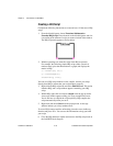
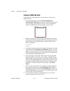
11. Run the VI. LabVIEW launches HiQ and a new HiQ window appears,
labeled G in Notebook1, that displays the matrix. The values that make
up this matrix are displayed in the a indicator of your front panel in
LabVIEW.
The second parameter in the CreateView function specifies whether to
pause execution of the HiQ script while the view is visible. The HiQ script
in Step 2 does not finish until you click the Continue button in the HiQ
window to dismiss the view.
12. Change the
true parameter to false and re-run the VI to see the
difference.