


109
CHAPTER 5 CPU ARCHITECTURE
70
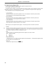
IEPSW Z RBS1 AC RBS0 0 ISP CY
5.2 Processor Registers
The
µ
PD78054 and 78054Y subseries units incorporate the following processor registers.
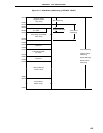
5.2.1 Control registers
The control registers control the program sequence, statuses and stack memory. The control registers consist
of a program counter (PC), a program status word (PSW) and a stack pointer (SP).
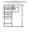
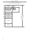
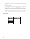
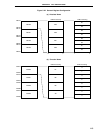
(1) Program counter (PC)
The program counter is a 16-bit register which holds the address information of the next program to be
executed.
In normal operation, the PC is automatically incremented according to the number of bytes of the instruction
to be fetched. When a branch instruction is executed, immediate data and register contents are set.
RESET input sets the reset vector table values at addresses 0000H and 0001H to the program counter.
Figure 5-17. Program Counter Configuration
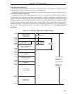
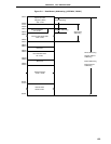
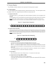
(2) Program status word (PSW)
The program status word is an 8-bit register consisting of various flags to be set/reset by instruction execution.
Program status word contents are automatically stacked upon interrupt request generation or PUSH PSW
instruction execution and are automatically reset upon execution of the RETB, RETI and POP PSW
instructions.
RESET input sets the PSW to 02H.
Figure 5-18. Program Status Word Configuration
(a) Interrupt enable flag (IE)
This flag controls the interrupt request acknowledge operations of the CPU.
When IE = 0, all interrupts except the non-maskable interrupt are disabled (DI status).
When IE = 1, interrupts are enabled (EI status). At this time, acknowledgment of interrupts is controlled
with an inservice priority flag (ISP), an interrupt mask flag for various interrupt sources, and a priority
specify flag.
The interrupt enable flag is reset to 0 when the DI instruction is executed or when an interrupt is
acknowledged, and set to 1 when the EI instruction is executed.
(b) Zero flag (Z)
When the operation result is zero, this flag is set (1). It is reset (0) in all other cases.
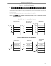
(c) Register bank select flags (RBS0 and RBS1)
These are 2-bit flags to select one of the four register banks.
In these flags, the 2-bit information which indicates the register bank selected by SEL RBn instruction
execution is stored.
PC
15
PC15
PC14
PC13
PC12
PC11
PC10
PC9
PC8
PC7
PC6
PC5
PC4
PC3
PC2
PC1
0
PC0