


455
CHAPTER 19 SERIAL INTERFACE CHANNEL 2
Note When SCK is set to 1 and the baud rate generator output is selected, the ASCK pin can be used
as an input/output port.
Caution The serial transmit/receive operation must be stopped before changing the operating
mode.
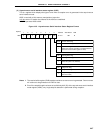
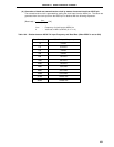
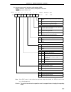
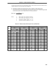
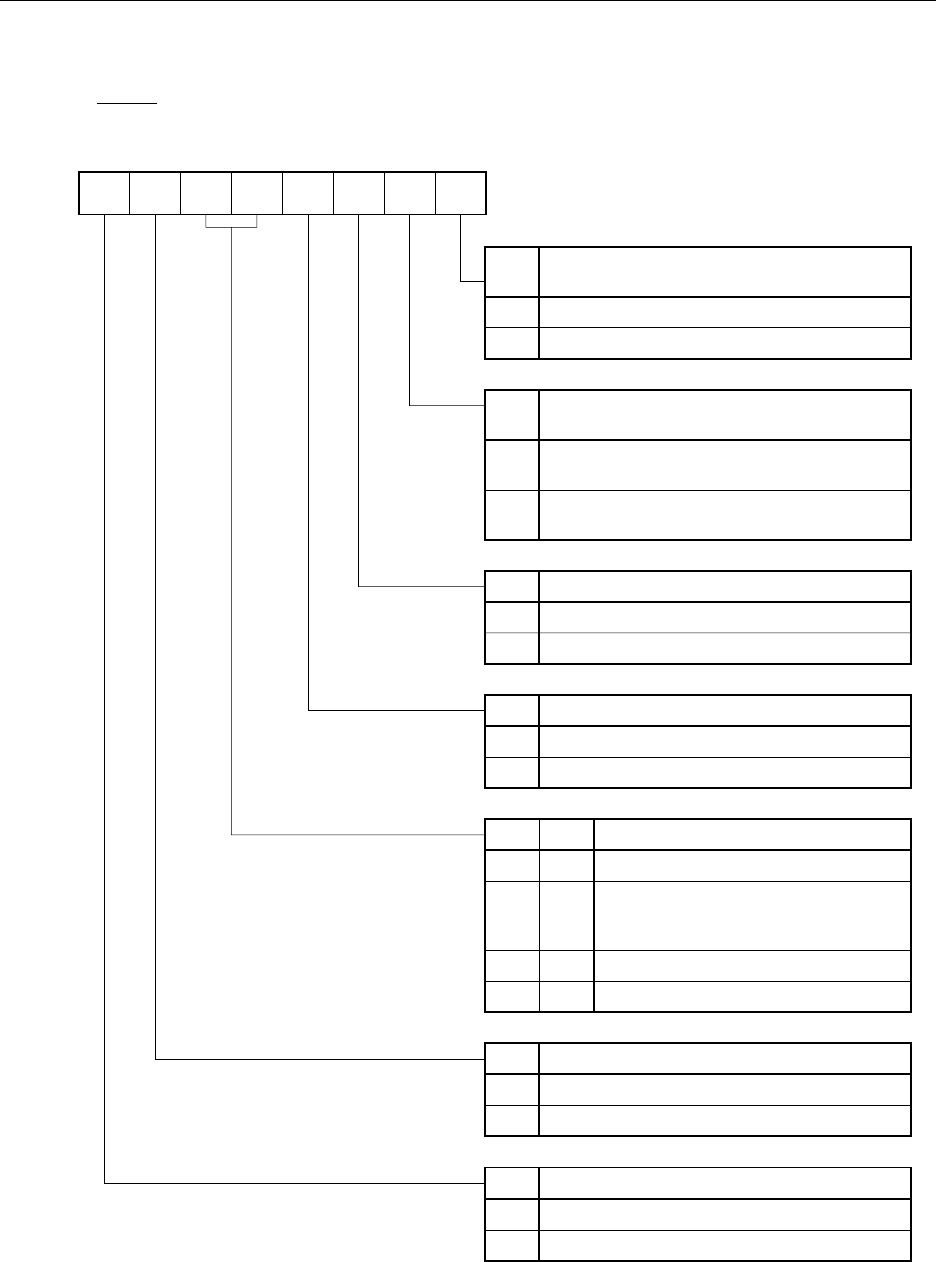
(b) Asynchronous serial interface mode register (ASIM)
ASIM is set with a 1-bit or 8-bit memory manipulation instruction.
RESET input sets ASIM to 00H.
<6>543210<7>
Symbol
ASIM TXE RXE PS1 PS0 CL SL ISRM SCK
FF70H 00H R/W
Address After Reset R/W
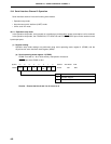
SCK
0
1
Clock Selection in Asynchronous Serial Interface
Mode
Input clock from off-chip to ASCK pin
Dedicated baud rate generator output
Note
ISRM
0
1
Control of Reception Completion Interrupt Request
in Case of Error Generation
Reception completion interrupt request generated
in case of error generation
Reception completion interrupt request not
generated in case of error generation
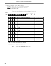
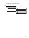
SL Transmit Data Stop Bit Length Specification
CL
1
Character Length Specification
7 bits
8 bits
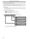
RXE
0
1
Receive Operation Control
Receive operation stopped
Receive operation enabled
TXE
0
1
Transmit Operation Control
Transmit operation stopped
Transmit operation enabled
PS1
0
1
0 1 bit
1 2 bits
0
Parity Bit Specification
No Parity
Even parity
PS0
0
1
0 parity always added in transmission
No parity test in reception (parity error not
generated)
0
1
1 Odd parity
0