


187
CHAPTER 8 16-BIT TIMER/EVENT COUNTER
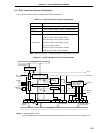
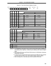
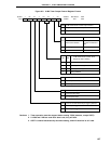
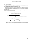
0 OSPT OSPE TOC04
LVS0 LVR0 TOC01 TOE0
7 <6> <5> 4 <3> <2> 1 <0>Symbol
TOC0
FF4EH 00H R/W
Address After Reset R/W
TOE0
16-Bit Timer/Event Counter Output Control
0
Output disabled (Port mode)
1
Output enabled
TOC01
0
1
In PWM Mode In Other Modes
Active level selection
Timer output F/F control
by match of CR00 and
TM0
Active high
Active low
Inversion operation disabled
Inversion operation enabled
LVS0 LVR0
16-Bit Timer/Event Counter Timer
Output F/F Status Setting
0 0 No change
0 1 Timer output F/F reset (0)
1 0 Timer output F/F set (1)
1 1 Setting prohibited
TOC04 Timer output F/F control by match of CR01 and TM0
0 Inversion operation disabled
1 Inversion operation enabled
OSPE One-Shot Pulse Output Control
0 Continuous pulse output
1 One-shot pulse output
OSPT Control of One-Shot Pulse Output Trigger by Software
0 One-shot pulse trigger not used
1 One -shot pulse trigger used
Figure 8-6. 16-Bit Timer Output Control Register Format
Cautions 1. Timer operation must be stopped before setting TOC0 (however, except OSPT).
2. If LVS0 and LVR0 are read after data is set, they will be 0.
3. OSPT is cleared automatically after data setting, and will therefore be 0 if read.