


172
CHAPTER 7 CLOCK GENERATOR
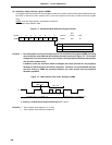
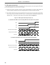
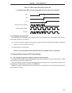
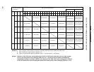
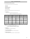
Table 7-3. Maximum Time Required for CPU Clock Switchover
×
×
××
1
0
0
0
1100
100
01000
CSS
00
0
0
×
PCC0
PCC1
PCC2
1
×
1
PCC0
CSS
PCC2 PCC1
0
00
0
11
0
0
0
1
0
0
0
0
1
×
1
×
×
1
8 instructions
2 instructions
4 instructions
4 instructions
16 instructions
2 instructions
8 instructions
4 instructions
4 instructions
2 instructions
16 instructions
16 instructions
16 instructions
8 instructions
8 instructions
2 instructions
f
X/2fXT instruction
(77 instructions)
f
X/4fXT instruction
(39 instructions)
f
X/8f
XT instruction
(20 instructions)
f
X/32fXT
instruction
(5 instructions)
fX/16fXT
instruction
(10 instructions)
f
X/4fXT instruction
(39 instructions)
f
X/8fXT instruction
(20 instructions)
f
X/32f
XT instruction
(5 instructions)
fX/16f
XT instruction
(10 instructions)
f
X/64fXT instruction
(3 instructions)
MSC = 1
MSC = 0
Set Values After Switchover
Set Values before
Switchover
CSS CSS CSS
CSS
CSS
1 instruction
1 instruction
1 instruction
1 instruction
1 instruction1 instruction1 instruction
CSS
1 instruction
1 instruction
Remarks 1. One instruction is the minimum instruction execution time with the pre-switchover CPU clock.
2. MCS: Oscillation mode selection register bit 0
3. Figures in parentheses apply to operation with f
X = 5.0 MHz and f
XT = 32.768 kHz.
Caution Selection of the CPU clock cycle scaling factor (PCC0 to PCC2) and switchover from the main system
clock to the subsystem clock (changing CSS from 0 to 1) should not be performed simultaneously.
Simultaneous setting is possible, however, for selection of the CPU clock cycle scaling factor (PCC0 to
PCC2) and switchover from the subsystem clock to the main system clock (changing CSS from 1 to 0).
PCC0
PCC1
PCC2
PCC1
PCC2 PCC0
PCC1
PCC2 PCC0
PCC1
PCC2 PCC0
PCC1
PCC2 PCC0
PCC1
PCC2 PCC0