


204
CHAPTER 8 16-BIT TIMER/EVENT COUNTER
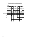
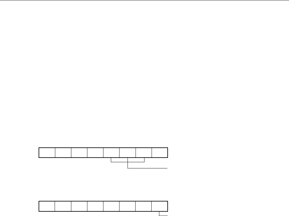
CRC0 00/10/100000
CRC00CRC01CRC02
CR00 set as compare register
TMC0 00/1110000
OVF0TMC01TMC02TMC03
Clear & start with match of TM0 and CR00
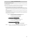
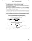
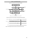
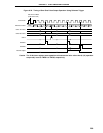
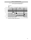
8.5.5 External event counter operation
The external event counter counts the number of external clock pulses to be input to the TI00/P00 pin with the
16-bit timer register (TM0).
TM0 is incremented each time the valid edge specified with the external interrupt mode register 0 (INTM0) is input.
When the TM0 counted value matches the 16-bit capture/compare register 00 (CR00) value, TM0 is cleared to
0 and the interrupt request signal (INTTM00) is generated.
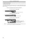
Set the value other than 0000H to CR00 (1-pulse count operation cannot be performed).
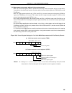
The rising edge, the falling edge or both edges can be selected with bits 2 and 3 (ES10 and ES11) of INTM0.
Because operation is carried out only after the valid edge is detected twice by sampling at the interval selected
with the sampling clock select register (SCS), noise with short pulse widths can be removed.
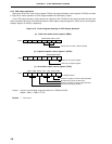
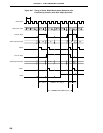
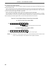
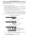
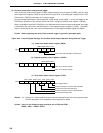
Figure 8-26. Control Register Settings in External Event Counter Mode
(a) 16-bit timer mode control register (TMC0)
(b) Capture/compare control register 0 (CRC0)
Remark 0/1: Setting 0 or 1 allows another function to be used simultaneously with the external event
counter. See the description of the respective control registers for details.