


439
CHAPTER 19 SERIAL INTERFACE CHANNEL 2
19.1 Serial Interface Channel 2 Functions
Serial interface channel 2 has the following three modes.
• Operation stop mode
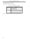
• Asynchronous serial interface (UART) mode
• 3-wire serial I/O mode
(1) Operation stop mode
This mode is used when serial transfer is not carried out to reduce power consumption.
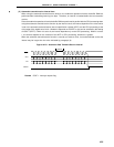
(2) Asynchronous serial interface (UART) mode
In this mode, one byte of data is transmitted/received following the start bit, and full-duplex operation is
possible.
A dedicated UART baud rate generator is incorporated, allowing communication over a wide range of baud
rates. In addition, the baud rate can be defined also by scaling the input clock to the ASCK pin.
The MIDI standard baud rate (31.25 kbps) can also be used by employing the dedicated UART baud rate
generator.
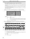
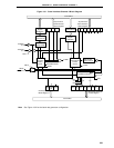
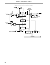
(3) 3-wire serial I/O mode (MSB-/LSB-first switchable)
In this mode, 8-bit data transfer is performed using three lines: the serial clock (SCK2), and serial data lines
(SI2, SO2).
In the 3-wire serial I/O mode, simultaneous transmission and reception is possible, increasing the data transfer
processing speed.
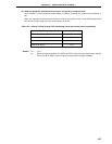
Either the MSB or LSB can be specified as the start bit for an 8-bit data serial transfer, allowing connection
to devices using either as the start bit.
The 3-wire serial I/O mode is useful for connection to peripheral I/Os and display controllers, etc., which
incorporate a conventional synchronous clocked serial interface, such as the 75X/XL series, 78K series, 17K
series, etc.
Caution In the 3-wire serial I/O mode of serial interface channel 2, only the output of the internal
baud rate generator can be used for the operation clock. It is not possible to input a clock
to pin SCK2 from external.