


371
CHAPTER 17 SERIAL INTERFACE CHANNEL 0 (
µ
PD78054Y Subseries)
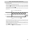
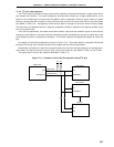
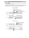
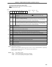
(f) Wait signal (WAIT)
The wait signal is output by a slave device to inform the master device that the slave device is in wait state due
to preparing for transmitting or receiving data.
During the wait state, the slave device continues to output the wait signal by keeping the SCL pin low to delay
subsequent transfers. When the wait state is released, the master device can start the next transfer. For the
releasing operation of slave devices, see section 17.4.5, “Cautions on Use of I
2
C Bus Mode.”
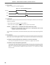
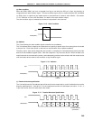
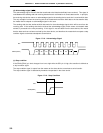
Figure 17-20. Wait Signal
(a) Wait of 8 Clock Cycles
(b) Wait of 9 Clock Cycles
SCL of
master device
D2 D1 D0
ACK
D7
Output by manipulating ACKT
6789 1 324
D6 D5 D4
Set low because slave device drives low,
though master device returns to Hi-Z state.
No wait is inserted after 9th clock cycle.
(and before master device starts next transfer.)
SCL of
slave device
SCL
SDA0(SDA1)
SCL of
master device
Set low because slave device drives low,
though master device returns to Hi-Z state.
SCL of
slave device
SCL
D2 D1 D0 ACK D7
Output based on the value set in ACKE in advance
6789 23
D6 D5
1
SDA0(SDA1)