


307
CHAPTER 16 SERIAL INTERFACE CHANNEL 0 (
µ
PD78054 Subseries)
16.4.3 SBI mode operation
SBI (Serial Bus Interface) is a high-speed serial interface in compliance with the NEC serial bus format.
SBI uses a single master device and employs the clocked serial I/O format with the addition of a bus configuration
function. This function enables devices to communicate using only two lines. Thus, when making up a serial bus
with two or more microcontrollers and peripheral ICs, the number of ports to be used and the number of wires on
the board can be decreased.
The master device outputs three kinds of data to slave devices on the serial data bus: “addresses” to select a device
to be communicated with, “commands” to instruct the selected device, and “data” which is actually required.
The slave device can identify the received data into “address”, “command”, or “data”, by hardware. This function
simplifies the application program to control serial interface channel 0.
The SBI function is incorporated into various devices including 75X/XL Series and 78K Series.
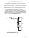
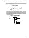
Figure 16-10 shows a serial bus configuration example when a CPU having a serial interface compliant with SBI
and peripheral ICs are used.
In SBI, the SB0 (SB1) serial data bus pin is an open-drain output pin and therefore the serial data bus line behaves
in the same way as the wired-OR configuration. In addition, a pull-up resistor must be connected to the serial data
bus line.
When the SBI mode is used, refer to (11) SBI mode precautions (d) described later.
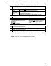
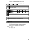
Figure 16-10. Example of Serial Bus Configuration with SBI
Caution When exchanging the master CPU/slave CPU, a pull-up resistor is necessary for the serial clock
line (SCK0) as well because serial clock line (SCK0) input/output switching is carried out
asynchronously between the master and slave CPUs.
Master CPU
SCK0
SB0 (SB1)
SCK0
SB0 (SB1)
SCK0
SB0 (SB1)
SCK0
SB0 (SB1)
Slave CPU
Address 1
Slave CPU
Address 2
Slave IC
Address N
Serial Clock
Serial Data Bus
•
•
•
•
•
•
V
DD