


331
CHAPTER 16 SERIAL INTERFACE CHANNEL 0 (
µ
PD78054 Subseries)
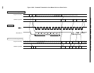
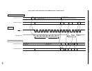
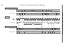
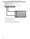
(9) Transfer start
Serial transfer is started by setting transfer data to the serial I/O shift register 0 (SIO0) when the following two
conditions are satisfied.
• Serial interface channel 0 operation control bit (CSIE0) = 1
• Internal serial clock is stopped or SCK0 is at high level after 8-bit serial transfer.
Cautions 1. If CSIE0 is set to “1” after data write to SIO0, transfer does not start.
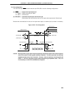
2. Because the N-ch open-drain output must be high-impedance state for data reception,
write FFH to SIO0 in advance.
However, when the wake-up function specify bit (WUP) = 1, the N-ch open-drain output
is always high-impedance state. Thus, it is not necessary to write FFH to SIO0.
3. If data is written to SIO0 when the slave is busy, the data is not lost.
When the busy state is cleared and SB0 (or SB1) input is set to the high level (READY)
state, transfer starts.
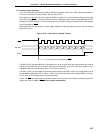
Upon termination of 8-bit transfer, serial transfer automatically stops and the interrupt request flag (CSIIF0)
is set.
Perform the following settings to the pins used for input/output of data (SB0 or SB1) after inputting RESET
before the first byte of serial transmission.
<1> Set the P25 and P26 output latches to 1.
<2> Set bit 0 (RELT) of the serial bus interface control register (SBIC) to 1.
<3> Reset the P25 and P26 output latches from 1 to 0.