


527
CHAPTER 23 STANDBY FUNCTION
23.2 Standby Function Operations
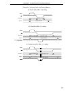
23.2.1 HALT mode
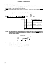
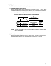
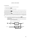
(1) HALT mode set and operating status
The HALT mode is set by executing the HALT instruction. It can be set with the main system clock or the
subsystem clock.
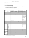
The operating status in the HALT mode is described below.
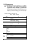
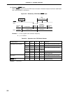
Table 23-1. HALT Mode Operating Status
Setting of HALT Mode On Execution of HALT Instruction during Main On Execution of HALT Instruction during
System Clock Operation Subsystem Clock Operation
Without subsystem With subsystem When main system clock When main system
Item clock
Note 1
clock
Note 1
continues oscillation clock stops oscillation
Clock generator Both main system and subsystem clocks can be oscillated. Clock supply to the CPU stops.
CPU Operation stops.
Port (output latch) Status before HALT mode setting is held.
16-bit timer/event counter Operable. Operable when watch
timer output is selected
as count clock (f
XT is
selected as count clock
of watch timer) or when
TI00 is selected.
8-bit timer/event counter Operable. Operable when TI1 or
TI2 is selected as
count clock.
Watch timer Operable when f
XX/2
7
is Operable. Operable when fXT is
selected as count clock. selected as count clock.
Watchdog timer Operable. Operation stops.
A/D converter Operable. Operation stops.
D/A converter Operable.
Real-time output port Operable.
Serial interface Other than Operable. Operable when
automatic external SCK is used.
transmit/
receive
function
Automatic Operation stops.
transmit/
receive
function
External interrupt INTP0 INTP0 is operable when clock supplied for peripheral hardware is selected Operation stops.
as sampling clock (fXX/2
5
, fXX/2
6
, fXX/2
7
).
INTP1-INTP6 Operable.
Bus line for AD0-AD7 High impedance.
external
A0-A15 Status before HALT mode setting is held.
expansion
ASTB Low level.
WR, RD High level.
WAIT High impedance.
Notes 1. Including when external clock is not supplied
2. Including when external clock is supplied