


432
CHAPTER 18 SERIAL INTERFACE CHANNEL 1
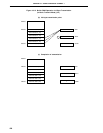
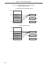
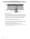
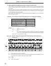
Figure 18-20. Busy Signal and Wait Cancel (when BUSY0 = 0)
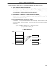
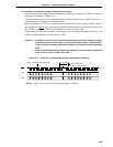
(b) Busy & strobe control option
Strobe control is a function for synchronizing the sending and receiving of data between a master device
and slave device. When sending or receiving of 8 bit data ends, the strobe signal is output by the master
device from pin STB/P23. Through this means, the slave device can know the timing of the end of master
data transmission. Therefore, even if there is noise in the serial clock and bit slippage occurs,
synchronization is maintained and bit slippage has no effect on transmission of the next byte.
In the case that the strobe control option is used, the conditions shown below are necessary.
• Set bit 5 (ATE) of serial operation mode register 1 (CSIM1) at (1).
• Set bit 2 (STRB) of the auto data send and receive control register (ADTC) at (1).
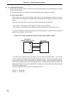
Normally, busy control and strobe control are used simultaneously as handshake signals. In this case,
together with output of the strobe signal from pin STB/P23, pin BUSY/P24 can be sampled and sending
or receiving can wait while the busy signal is being input.
If strobe control is not carried out, pin P23/STB can be used as a normal I/O port.
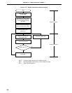
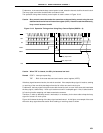
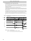
Operation timing when busy and strobe control are used is shown in Figure 18-21.
Furthermore, if strobe control is used, the interrupt request flag (CSIIF1), set when sending or receiving
ends, is set after the strobe signal is output.
SCK1
D7
SO1
SI1
D6
D5 D4 D3 D2 D1 D0 D7 D6 D5 D4 D3 D2 D1 D0
D7 D6 D5 D4 D3 D2 D1 D0 D7 D6 D5 D4 D3 D2 D1 D0
BUSY
(Active High)
1.5 clocks (min.)
BUSY Input Cancel
Wait
In the case where the busy
signal becomes inactive
directly when sampled
BUSY Input Effective