


368
CHAPTER 17 SERIAL INTERFACE CHANNEL 0 (
µ
PD78054Y Subseries)
(1) I
2
C bus mode functions
In the I
2
C bus mode, the following functions are available.
(a) Automatic identification of serial data
Slave devices automatically detect and identifies start condition, data, and stop condition signals sent in series
through the serial data bus.
(b) Chip selection by specifying device addresses
The master device can select a specific slave device connected to the I
2
C bus and communicate with it by
sending in advance the address data corresponding to the destination device.
(c) Wake-up function
An interrupt request is generated during slave operation when the received address matches the value of slave
address register (SVA). (the interrupt request also occurs when the stop condition is detected). Therefore,
CPUs other than the selected slave device on the I
2
C bus can perform independent operations during the
serial communication.
(d) Acknowledge signal (ACK) control function
The master device and a slave device send and receive acknowledge signals to confirm that the serial
communication has been executed normally.
(e) Wait signal (WAIT) control function
When a slave device is preparing for data transmission or reception and requires more waiting time, the slave
device outputs a wait signal on the bus to inform the master device of the wait status.
(2) I
2
C bus definition
This section describes the format of serial data communications and functions of the signals used in the I
2
C
bus mode.
First, the transfer timings of the start condition, data, and stop condition signals, which are output onto the
signal data bus of the I
2
C bus, are shown in Figure 17-14.
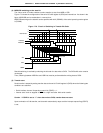
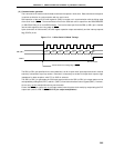
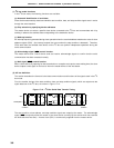
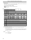
Figure 17-14. I
2
C Bus Serial Data Transfer Timing
The start condition, slave address, and stop condition signals are output by the master. The acknowledge
signal (ACK) is output by either the master or the slave device (normally by the device which has received
the 8-bit data that was sent). A serial clock (SCL) is continuously supplied from the master device.
1-7 8 9 1-7 8 9 1-7 8 9
Address R/W ACK
Data ACK Data ACK
SCL
Start
condition
SDA0(SDA1)
Stop
condition