


239
CHAPTER 9 8-BIT TIMER/EVENT COUNTERS 1 AND 2
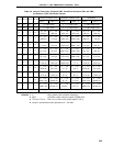
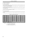
(2) 8-bit compare register 10 and 20 setting
The 8-bit compare registers 10 and 20 (CR10 and CR20) can be set to 00H.
Thus, when these 8-bit compare registers are used as event counters, one-pulse count operation can be
carried out.
When the 8-bit compare register is used as 16-bit timer/event counter, write data to CR10 and CR20 after
setting bit 0 (TCE1) of the 8-bit timer mode control register 1 to 0 and stopping timer operation.
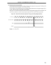
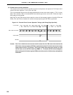
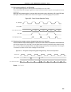
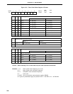
Figure 9-15. Event Counter Operation Timing
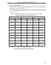
(3) Operation after compare register change during timer count operation
If the values after the 8-bit compare registers 10 and 20 (CR10 and CR20) are changed are smaller than those
of 8-bit timer registers (TM1 and TM2), TM1 and TM2 continue counting, overflow and then restart counting
from 0. Thus, if the value (M) after CR10 and CR20 change is smaller than value (N) before the change, it
is necessary to restart the timer after changing CR10 and CR20.
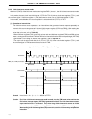
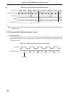
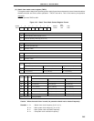
Figure 9-16. Timing after Compare Register Change during Timer Count Operation
Remark N > X > M
TI1, TI2, Input
CR10, CR20
TM1, TM2 Count Value
TO1, TO2
Interrupt Request Flag
00H
00H 00H 00H 00H
Count Pulse
CR10, CR20
TM1, TM2 Count Value
X-1 X FFH 00H 01H 02H
MN