


173
CHAPTER 7 CLOCK GENERATOR
V
DD
RESET
Interrupt
Request
Signal
System Clock
CPU Clock
Wait (26.2 ms : 5.0 MHz)
Internal Reset Operation
Minimum
Speed
Operation
Maximum Speed
Operation
Subsystem Clock
Operation
f
XX
f
XX
f
XT
f
XX
High-Speed
Operation
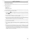
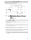
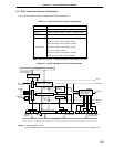
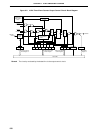
7.6.2 System clock and CPU clock switching procedure
This section describes switching procedure between system clock and CPU clock.
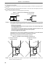
Figure 7-10. System Clock and CPU Clock Switching
(1) The CPU is reset by setting the RESET signal to low level after power-on. After that, when reset is released
by setting the RESET signal to high level, main system clock starts oscillation. At this time, oscillation
stabilization time (2
17
/fX) is secured automatically.
After that, the CPU starts executing the instruction at the minimum speed of the main system clock (12.8
µ
s when
operated at 5.0 MHz).
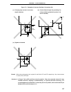
(2) After the lapse of a sufficient time for the VDD voltage to increase to enable operation at maximum speeds,
the processor clock control register (PCC) and oscillation mode selection register (OSMS) are rewritten and
the maximum-speed operation is carried out.
(3) Upon detection of a decrease of the V
DD voltage due to an interrupt request signal, the main system clock
is switched to the subsystem clock (which must be in an oscillation stable state).
(4) Upon detection of V
DD voltage reset due to an interrupt request signal, 0 is set to the bit 7 (MCC) of PCC and
oscillation of the main system clock is started. After the lapse of time required for stabilization of oscillation,
the PCC and OSMS are rewritten and the maximum-speed operation is resumed.
Caution When subsystem clock is being operated while main system clock was stopped, if switching to
the main system clock is made again, be sure to switch after securing oscillation stable time by
software.