


284
CHAPTER 15 D/A CONVERTER
0
7
0
6
DAM5 DAM4
4
0
3 2 <1> <0>
FF98H
Address
DAM
Symbol
0
DACE1 DACE0
5
00H
After
Reset
R/W
R/W
DAM5
0
1
D/A Converter Channel 1 Operating Mode
Normal mode
Real-time output mode
DACE0
0
1
D/A Converter Channel 0 Control
D/A conversion stop
D/A conversion enable
DACE1
0
1
D/A Converter Channel 1 Control
D/A conversion stop
D/A conversion enable
DAM4
0
1
D/A Converter Channel 0 Operating Mode
Normal mode
Real-time output mode
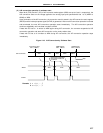
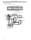
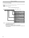
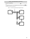
15.3 D/A Converter Control Registers
The D/A converter mode register (DAM) controls the D/A converter. This register sets D/A converter operation
enable/stop.
The DAM is set with a 1-bit or 8-bit memory manipulation instruction.
RESET input sets this register to 00H.
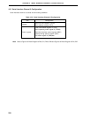
Figure 15-2. D/A Converter Mode Register Format
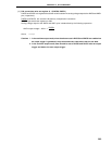
Cautions 1. When using the D/A converter, a dual-function port pin should be set to the input mode, and
a pull-up resistor should be disconnected.
2. Always set bits 2, 3, 6, and 7 to 0.
3. When D/A conversion is stopped, the output state is high-impedance.
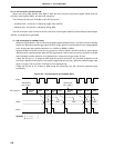
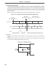
4. The output triggers are INTTM1 and INTTM2 for channel 0 and channel 1, respectively, in the
real-time output mode.