


191
CHAPTER 8 16-BIT TIMER/EVENT COUNTER
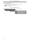
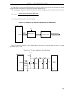
0 0 0 0 0 0/1 0/1 0
CRC02 CRC01 CRC00
CRC0
CR00 set as compare register
8.5 16-Bit Timer/Event Counter Operations
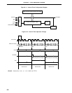
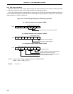
8.5.1 Interval timer operations
Setting the 16-bit timer mode control register (TMC0) and capture/compare control register 0 (CRC0) as shown
in Figure 8-10 allows operation as an interval timer. Interrupt requests are generated repeatedly using the count value
set in 16-bit capture/compare register 00 (CR00) beforehand as the interval.
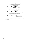
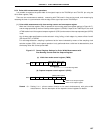
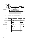
When the count value of the 16-bit timer register (TM0) matches the value set to CR00, counting continues with
the TM0 value cleared to 0 and the interrupt request signal (INTTM00) is generated.
Count clock of the 16-bit timer/event counter can be selected with bits 4 to 6 (TCL04 to TCL06) of the timer clock
select register 0 (TCL0).
For the operation when the value of the compare register is changed during the timer count operation, refer to
8.6 16-Bit Timer/Event Counter Precautions (3).
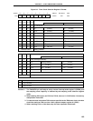
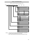
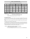
Figure 8-10. Control Register Settings for Interval Timer Operation
(a) 16-bit timer mode control register (TMC0)
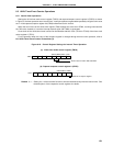
(b) Capture/compare control register 0 (CRC0)
Remark 0/1 : Setting 0 or 1 allows another function to be used simultaneously with the interval timer. See
the description of the respective control registers for details.
0000110/10
TMC03 TMC02 TMC01 OVF0
TMC0
Clear & start on match TM0 and CR00