


182
CHAPTER 8 16-BIT TIMER/EVENT COUNTER
Caution If the valid edge of the TIO0/P00 pin is input while CR01 is read, CR01 does not perform the
capture operation and retains the current data. However, the interrupt request flag (PIF0)
is set.
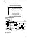
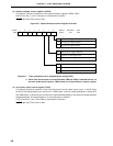
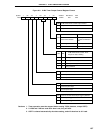
(3) 16-bit timer register (TM0)
TM0 is a 16-bit register which counts the count pulses.
TM0 is read by a 16-bit memory manipulation instruction. When TM0 is read, capture/compare register 01
(CR01) should first be set as a capture register.
RESET input sets TM0 to 0000H.
Caution As the value of TM0 is read via CR01, the value of CR01 previously set is lost.
8.4 16-Bit Timer/Event Counter Control Registers
The following seven types of registers are used to control the 16-bit timer/event counter.
• Timer clock select register 0 (TCL0)
• 16-bit timer mode control register (TMC0)
• Capture/compare control register 0 (CRC0)
• 16-bit timer output control register (TOC0)
• Port mode register 3 (PM3)
• External interrupt mode register 0 (INTM0)
• Sampling clock select register (SCS)
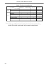
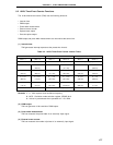
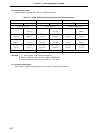
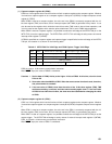
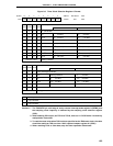
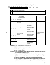
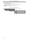
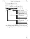
(1) Timer clock select register 0 (TCL0)
This register is used to set the count clock of the 16-bit timer register.
TCL0 is set with a 1-bit or 8-bit memory manipulation instruction.
RESET input sets TCL0 value to 00H.
Remark TCL0 has the function of setting the PCL output clock in addition to that of setting the count clock
of the 16-bit timer register.