


553
CHAPTER 26
µ
PD78P054, 78P058
(3) Standby mode
Setting CE to H sets the standby mode.
In this mode, data output becomes high impedance irrespective of the status of OE.
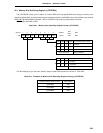
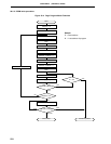
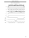
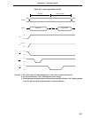
(4) Page data latch mode
Setting CE to H, PGM to H, and OE to L at the start of the page write mode sets the page data latch mode.
In this mode, 1-page 4-byte data is latched in the internal address/data latch circuit.
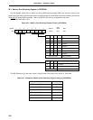
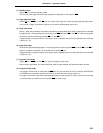
(5) Page write mode
After a 1-page 4-byte address and data are latched by the page data latch mode, a page write is executed
by applying a 0.1-ms program pulse (active-low) to the PGM pin while CE=H and OE=H. After this, program
verification can be performed by setting CE to L and OE to L.
If programming is not performed by one program pulse, repeated write and verify operations are executed
X times (X ≤ 10).
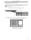
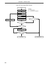
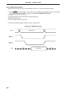
(6) Byte write mode
A byte write is executed by applying a 0.1-ms program pulse (active-low) to the PGM pin while CE=L and OE=H.
After this, program verification can be performed by setting OE to L.
If programming is not performed by one program pulse, repeated write and verify operations are executed
X times (X ≤ 10).
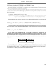
(7) Program verify mode
Setting CE to L, PGM to H, and OE to L sets the program verify mode.
After writing is performed, this mode should be used to check whether the data was written correctly.
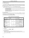
(8) Program inhibit mode
The program inhibit mode is used when the OE pins, V
PP pins and pins D0 to D7 of multiple
µ
PD78P054s
or 78P058s are connected in parallel and any one of these devices must be written to.
The page write mode or byte write mode described above is used to perform a write. At this time, the write
is not performed on the device which has the PGM pin driven high.