


298
CHAPTER 16 SERIAL INTERFACE CHANNEL 0 (
µ
PD78054 Subseries)
(3) Serial bus interface control register (SBIC)
This register sets serial bus interface operation and displays statuses.
SBIC is set with a 1-bit or 8-bit memory manipulation instruction.
RESET input sets SBIC to 00H.
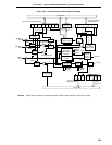
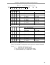
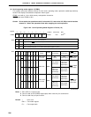
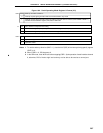
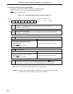
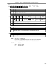
Figure 16-5. Serial Bus Interface Control Register Format (1/2)
Note Bits 2, 3, and 6 (RELD, CMDD and ACKD) are read-only bits.
Remarks 1. Bits 0, 1, and 4 (RELD, CMDT, and ACKT) are 0 when read after data setting.
2. CSIE0: Bit 7 of serial operating mode register 0 (CSIM0)
<6> <5> <4> <3> <2> <1> <0><7>
Symbol
SBIC BSYE ACKD ACKE ACKT CMDD RELD CMDT RELT
RELT
Used for bus release signal output.
When RELT = 1, SO0 Iatch is set to 1. After SO0 latch setting, automatically cleared to 0.
Also cleared to 0 when CSIE0 = 0.
R/W
FF61H 00H R/W
Note
Address After Reset R/W
CMDT
Used for command signal output.
When CMDT = 1, SO0 Iatch is cleared to (0). After SO0 latch clearance, automatically cleared to 0.
Also cleared to 0 when CSIE0 = 0.
R/W
R
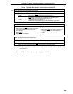
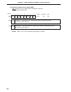
RELD Bus Release Detection
Set Conditions (RELD =1)Clear Conditions (RELD = 0)
• When bus release signal (REL) is detected
• When transfer start instruction is executed
• If SIO0 and SVA values do not match in
address reception
• When CSIE0 = 0
• When RESET input is applied
R
CMDD Command Detection
Clear Conditions (CMDD = 0)
• When transfer start instruction is executed
• When bus release signal (REL) is detected
• When CSIE0 = 0
• When RESET input is applied
Set Conditions (CMDD = 1)
• When command signal (CMD) is detected
ACKT
Acknowledge signal is output in synchronization with the falling edge clock of SCK0 just after execution
of the instruction to be set to 1, and after acknowledge signal output, automatically cleared to 0.
Used as ACKE = 0. Also cleared to 0 upon start of serial interface transfer or when CSIE0 = 0.
R/W