


490
CHAPTER 21 INTERRUPT AND TEST FUNCTIONS
<7>
PMK6
Symbol
MK0L
<6>
PMK5
<5>
PMK4
<4>
PMK3
<3>
PMK2
<2>
PMK
<1>
PMK
<0>
TMMK4
Address
FFE4H FFH
After
Reset
R/W
R/W
× ×
MK
×
0
1
Interrupt Servicing Control
Interrupt servicing enabled
Interrupt servicing disabled
<7>
TMMK01
MK0H
<6>
TMMK00
<5>
TMMK3
<4>
STMK
<3>
SRMK
<2>
SERMK
<1>
CSIMK1
<0>
CSIMK0
<7>
WTMK
Note
MK1L
6
1
5
1
4
1
3
1
<2>
ADMK
<1>
TMMK2
<0>
TMMK1
FFE5H FFH R/W
FFE6H FFH R/W
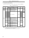
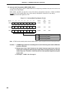
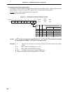
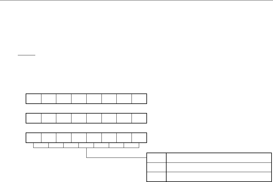
Note WTMK controls standby mode release enable/disable. It does not perform control of interrupt function.
Cautions 1. If TMMK4 flag is read when a watchdog timer is used in watchdog timer mode 1, MK0 value
becomes undefined.
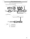
2. Because port 0 has a dual function as the external interrupt request input, when the
output level is changed by specifying the output mode of the port function, an interrupt
request flag is set. Therefore, 1 should be set in the interrupt mask flag before using the
output mode.
3. Set always 1 in MK1L bits 3 through 6.
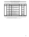
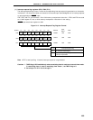
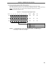
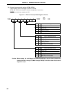
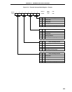
(2) Interrupt mask flag registers (MK0L, MK0H, MK1L)
The interrupt mask flag is used to enable/disable the corresponding maskable interrupt service and to set
standby clear enable/disable.
MK0L, MK0H, and MK1L are set with a 1-bit or 8-bit memory manipulation instruction. If MK0L and MK0H
are used as a 16-bit register MK0, use a 16-bit memory manipulation instruction for the setting.
RESET input sets these registers to FFH.
Figure 21-3. Interrupt Mask Flag Register Format