


367
CHAPTER 17 SERIAL INTERFACE CHANNEL 0 (
µ
PD78054Y Subseries)
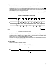
17.4.4 I
2
C bus mode operation
The I
2
C bus mode is provided for when communication operations are performed between a single master device
and multiple slave devices. This mode configures a serial bus that includes only a single master device, and is
based on the clocked serial I/O format with the addition of bus configuration functions, which allows the master
device to communicate with a number of (slave) devices using only two lines: serial clock (SCL) line and serial data
bus (SDA0 or SDA1) line. Consequently, when the user plans to configure a serial bus which includes multiple
microcontrollers and peripheral devices, using this configuration results in reduction of the required number of port
pins and on-board wires.
In the I
2
C bus specification, the master sends start condition, data, and stop condition signals to slave devices
through the serial data bus, while slave devices automatically detect and distinguish the type of signals due to the
signal detection function incorporated as hardware. This function simplifies the application program to control I
2
C
bus.
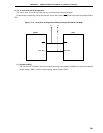
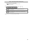
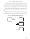
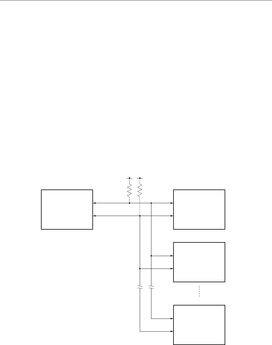
An example of a serial bus configuration is shown in Figure 17-13. This system below is composed of CPUs and
peripheral ICs having serial interface hardware that complies with the I
2
C bus specification.
Note that pull-up resistors are required to connect to both serial clock line and serial data bus line, because open-
drain buffers are used for the serial clock pin (SCL) and the serial data bus pin (SDA0 or SDA1) on the I
2
C bus.
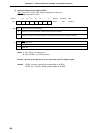
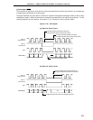
The signals used in the I
2
C bus mode are described in Table 17-4.
Figure 17-13. Example of Serial Bus Configuration Using I
2
C Bus
SCL
SDA0(SDA1)
SCL
SDA0(SDA1)
SCL
SDA0(SDA1)
SCL
SDA
Slave IC
Slave CPU2
Slave CPU1
Master CPU
V
DD
Serial clock
Serial data bus
V
DD