


507
CHAPTER 21 INTERRUPT AND TEST FUNCTIONS
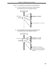
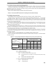
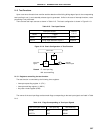
Internal bus
MK
IF
Test input
signal
Standby
release signal
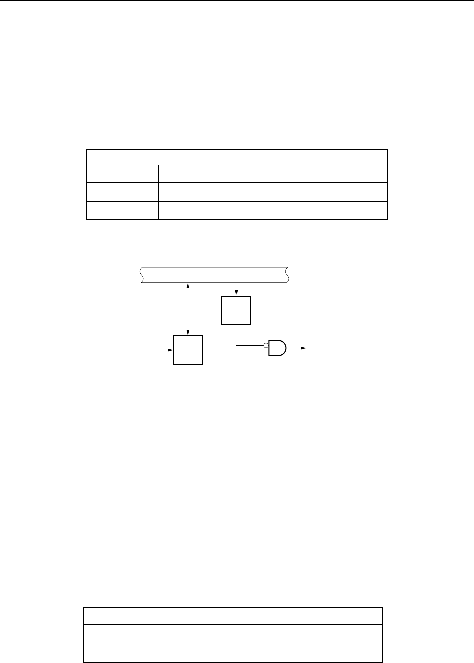
21.5 Test Functions
Upon occurrence of watch timer overflow and the detection of the falling falling edge of port 4, the corresponding
test input flag is set (1) and a standby release signal is generated. Unlike in the case of interrupt functions, vector
processing is not performed.
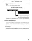
There are two test input sources as shown in Table 21-5. The basic configuration is shown in Figure 21-18.
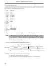
Table 21-5. Test Input Factors
Test Input Factors
Name Trigger
INTWT Watch timer overflow Internal
INTPT4 Falling edge detection at port 4 External
Figure 21-18. Basic Configuration of Test Function
Remark IF: test input flag
MK: test mask flag
21.5.1 Registers controlling the test function
The test function is controlled by the following three registers.
• Interrupt request flag register 1L (IF1L)
• Interrupt mask flag register 1L (MK1L)
• Key return mode register (KRM)
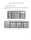
The names of the test input flags and test mask flags corresponding to the test input signals are listed in Table
21-6.
Table 21-6. Flags Corresponding to Test Input Signals
Test input signal name Test input flag Test mask flag
INTWT WTIF WTMK
INTPT4 KRIF KRMK
Internal/
external