


Reference Manual for the ProSafe Wireless 802.11g Firewall/Print Server Model FWG114P v2
NETGEAR VPN Configuration FVS318 or FVM318 to FWG114P v2 G-3
201-10301-02, May 2005
2.
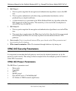
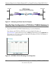
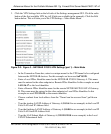
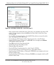
Click the VPN Settings link on the left side of the Settings management GUI. Click the radio
button of the first available VPN leg (all 8 links are available in the example). Click the Edit
button below. This will take you to the VPN Settings – Main Mode Menu.
Figure G-3: Figure 3 – NETGEAR FVS318 VPN Settings (part 1) – Main Mode
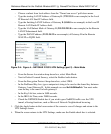
– In the Connection Name box, enter in a unique name for the VPN tunnel to be configured
between the NETGEAR devices. For this example we have used toFVS328.
– Enter a Local IPSec Identifier name for the NETGEAR FVS318 Gateway A. This name
must be entered in the other endpoint as Remote IPSec Identifier. In this example we used
14.15.16.17 as the local identifier.
– Enter a Remote IPSec Identifier name for the remote NETGEAR FWG114P v2 Gateway
B. This name must be entered in the other endpoint as Local IPSec Identifier. In this
example we used 22.23.24.25 as the remote identifier.
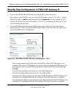
– Choose a subnet from local address from the “Tunnel can be accessed from” pull-down
menu.
– Type the starting LAN IP Address of Gateway A (10.5.6.1 in our example) in the Local IP
Local LAN start IP Address field.
– Type the finishing LAN IP Address of Gateway A (0.0.0.0 in our example) in the Local IP
Local LAN finish IP Address field.
– Type the LAN Subnet Mask of Gateway A (255.255.255.0 in our example) in the Local
LAN IP Subnetmask field.