150
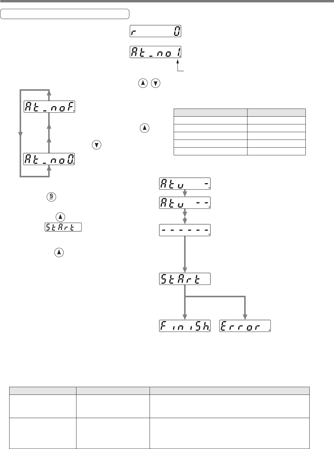
Normal Mode Auto-Gain Tuning
(1) Turn to the normal auto-gain tuning
mode from the monitor mode, by
pressing the SET button, then press
the mode switching button three times.
For details, refer to P.81, "Structure
of Each Mode" of Preparation.
(2) Enter the machine stiffness No. by pressing .
Display of rotational speed
of the motor (initial display)
Machine stiffness No.
Machine stiffness No. (High)
Machine stiffness No. (Low)
Tuning finishes
normally
Tuning error
Value changes toward the direction as
an arrow shows by pressing and
changes toward the reversed direction
by pressing .
(3) Shift to MONITOR/EXECUTION mode
by pressing .
(4) Operation at MONITOR/EXECUTION mode
Keep pressing until the display
changes to .
• Pin-29 of the connector, CN X5 to be
Servo-ON status.
Keep pressing for approx.3sec,
then bar increase as the right fig. shows.
The motor starts rotating.
For approx. 15 sec, the motor repeats
max. 5 cycles of CCW/CW rotation,
2 revolutions each direction per one cycle.
Tuning may finish before 5th cycles,
however, this is not an error.
(5) Write the gain value to EEPROM to prevent
them from being lost due to the power shut off.
Drive method
Ball screw direct connection
Ball screw + timing belt
Timing belt
Gear, Rack & Pinion
Others, low stiffness machine
Machine stiffness No.
8 to 14
6 to 12
4 to 10
2 to 8
0 to 8
Content
Display of error.
Value of parameter
related to gain (such as
SV/Pr10) is kept as same
as before the execution.
Cause
One of alarm, Servo-OFF or
deviation counter clear has
occurred.
Load inertia cannot be identi-
fied.
Measure
• Avoid an operation near the limit switch or home sensor switch.
• Turn to Servo-ON.
• Release the deviation counter clear
• Lower SV.Pr10 to 10 and SV.Pr11 to 50, then execute the
tuning.
• Adjust the gain manually. (Calculate the load inertia, and then
enter.)
How to Operate from the Console
<Caution>
Do not use the normal mode auto-gain tuning with the motor and driver alone. SV.Pr20 (Inertia ratio)
becomes to 0.
<Notes>


