


222
L 1
L 2
L 3
DC/DC
L1C
L2C
RB1
RB3
X4
X6
U
V
W
M
RE
N
P
+
Gate drive
RS232
+
-
+
+
-
A/D
Position
Speed
detection
Voltage
detection
Speed
deviation
amp.
PWM
circuit
RB2
DL1
DL2
Fuse
X5
Alarm
signal
Point
input
Pusle
output
Control
input
Control
output
Division/
mulitiplication
Deviation
counter
Position
deviation amp.
Front panel
Display
operation
control
Parameter control
Protective
curcuit
Error
detection
EEPROM
Sequence control
Torque
limit
Current
control
Division
processing
Encoder signal
processing
limit
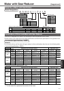
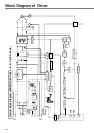
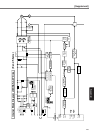
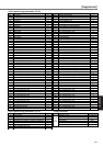
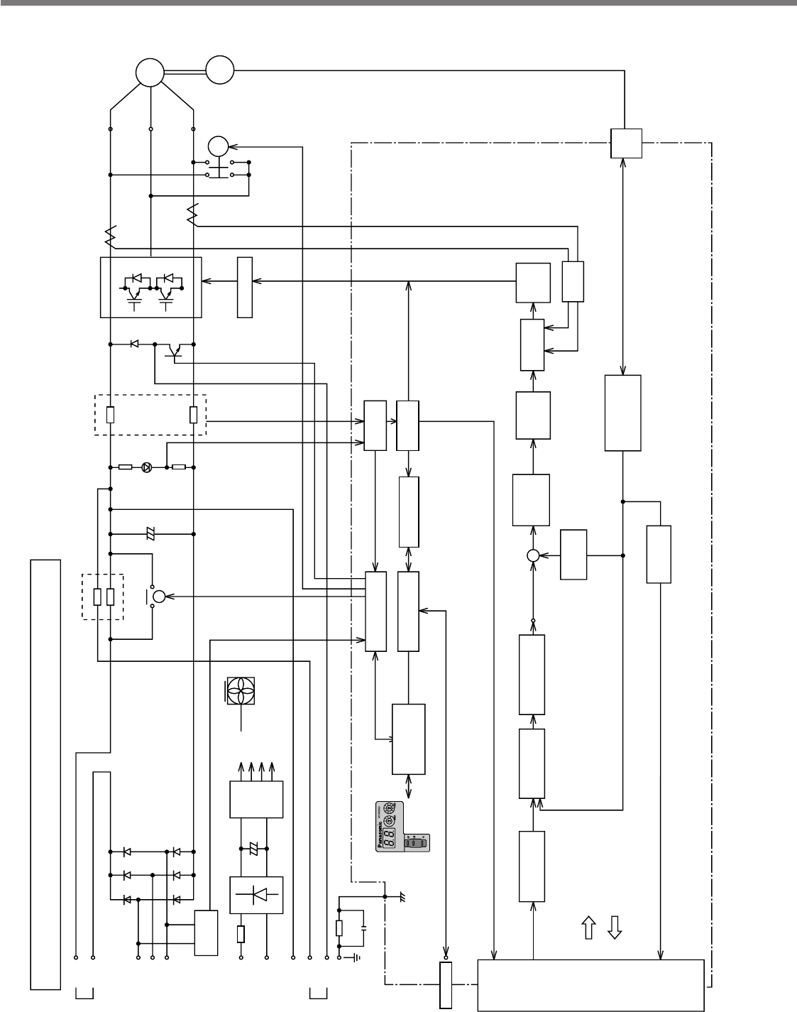
Internal Block Diagram of MINAS-A4P Driver (A, B, C and D-frame)
±12V
+5V
PS for gate drive
PS for RE
Fan
(D-frame only)
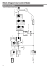
Block Diagram of Driver