


165
[When in Trouble]
When in Trouble
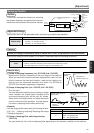
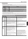
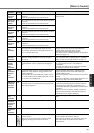
Warning Function
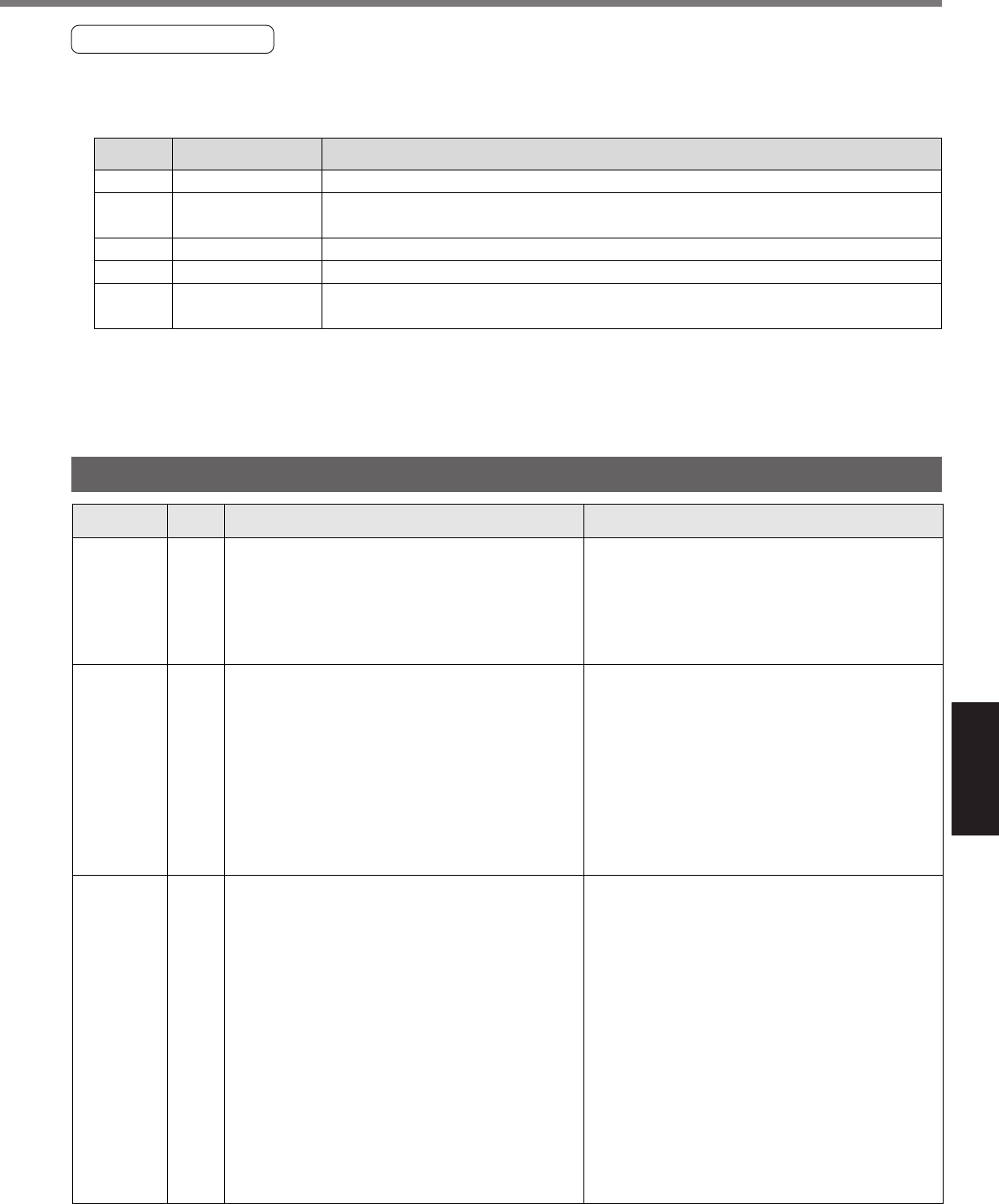
• In MINAS-A4P Series, a warning is given before a protection function works and you can check the ma-
chine status such as overload in advance.
When a warning has been given, a warning code below blinks slowly on the 7-segment LED at the front panel.
• When an overload warning or over-regeneration load warning has been given, referring to the counter-
measures taken by relevant protection function.
• When a battery warning has been given, replace the battery for absolute encoder with a new one. When
the battery has been replaced, perform Alarm Clear to the servo driver once to clear the battery alarm.
16
18
40
88
89
Overload warning
Over-regeneration
load warning
Battery warning
Fan lock warning
External scale alarm
Warning name Description
Warning
code number
The load has been 85% or more of the overload protection level.
The load has been 85% or more of the over-regenerative load protection level.
Voltage of a battery for absolute encoder has been approximately 3.2 V or less.
A fan has stopped for 1s or more.
An external scale temperature has been 65flC or more or signal intensity is insufficient
(mounting must be adjusted). This is enabled only for the full-closed control.
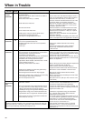
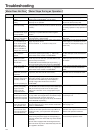
Protective Function (Detail of Error Code)
Protective
function
Causes Measures
Error
code No.
Voltage between P and N of the converter portion of the
control power supply has fallen below the specified value.
1)Power supply voltage is low. Instantaneous power
failure has occurred
2)
Lack of power capacity...Power supply voltage has
fallen down due to inrush current at the main power-on.
3)Failure of servo driver (failure of the circuit)
Measure the voltage between lines of connector (L1C
and L2C) and terminal block (r and t).
1)Increase the power capacity. Change the power
supply.
2)Increase the power capacity.
3)Replace the driver with a new one.
Control
power
supply
under-
voltage
protection
11
Over-
voltage
protection
12
Voltage between P and N of the converter portion of the
control power supply has exceeded the specified value
1)Power supply voltage has exceeded the permissible
input voltage. Voltage surge due to the phase-
advancing capacitor or UPS (Uninterruptible Power
Supply) have occurred.
2)Disconnection of the regeneration discharge resistor
3)External regeneration discharge resistor is not appro-
priate and could not absorb the regeneration energy.
4)Failure of servo driver (failure of the circuit)
Measure the voltage between lines of connector (L1,
L2 and L3).
1)Enter correct voltage. Remove a phase-advancing
capacitor.
2)Measure the resistance of the external resistor
connected between terminal P and B of the driver.
Replace the external resistor if the value is ∞.
3)Change to the one with specified resistance and
wattage.
4)Replace the driver with a new one.
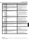
Main power
supply
under-
voltage
protection
13
Instantaneous power failure has occurred between L1 and
L3 for longer period than the preset time with SV.Pr6D
(Main power-off detection time) while SV.Pr65
(Undervoltage error response at main power-off) is set to
1. Or the voltage between P and N of the converter
portion of the main power supply has fallen below the
specified value during Servo-ON.
1)Power supply voltage is low. Instantaneous power
failure has occurred
2)Instantaneous power failure has occurred.
3)Lack of power capacity...Power supply voltage has
fallen down due to inrush current at the main power-
on.
4)Phase lack...3-phase input driver has been operated
with single phase input.
5)Failure of servo driver (failure of the circuit)
Measure the voltage between lines of connector (L1,
L2 and L3).
1)
Increase the power capacity. Change the power supply.
Remove the causes of the shutdown of the magnetic
contactor or the main power supply, then re-enter the power.
2)
Set up the longer time to SV.Pr6D (Main power off
detecting time). Set up each phase of the power correctly.
3)Increase the power capacity. For the capacity, refer
to P.32, "Driver and List of Applicable Peripheral
Equipments" of Preparation.
4)Connect each phase of the power supply (L1, L2 and
L3) correctly. For single phase, 100V and 200V
driver, use L1 and L3.
5)Replace the driver with a new one.