


45
[Preparation]
Preparation
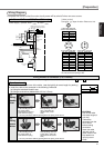
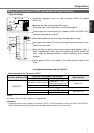
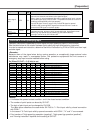
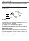
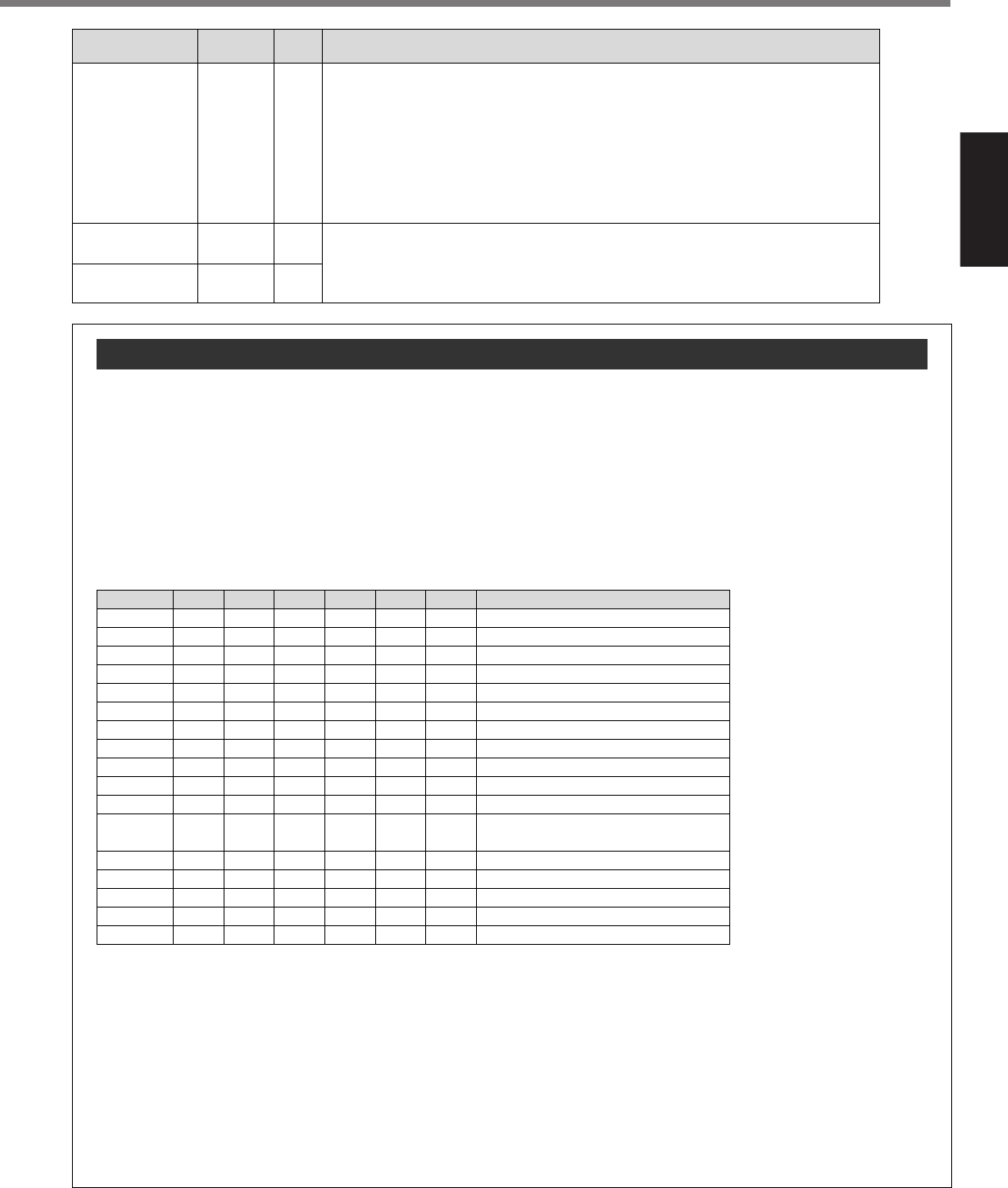
Operation instruction is specified by use of signal for point specifying input (P1IN to P32IN).
See the table below for the relation between point specifying input and operation instruction.
In order to execute an instruction, determine the kind of instruction by P1IN to P32IN, and then input
a strobe signal.
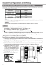
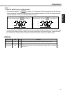
<Remarks>
Because down of the signal wires during moving operation or exceptionally larger external noise
disturbance may result in unexpected action, the protective equipments like limit sensors or
emergency stop input must be installed before using.
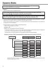
Ex) When SV.Pr57 = 3 (6 bits) is set
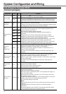
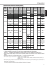
Overview of Point Spesifying Input
<Notes>
•H indicates the opened contact condition and L the closed contact condition.
•The number of point inputs can be set by SV.Pr57.
•The logic of point input can be changed by SV.Pr58.
The table above describes the case where SV.Pr58 is "1: Point input valid by closed connection
with COM–".
In the case of "0: Point input valid by opened connection with COM–", "H" and "L" are reversed.
•Point number of "High-speed jog operation (negative)", "High-speed jog operation (positive)",
and "Homing instruction" depends on the setting of SV.Pr57.
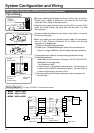
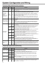
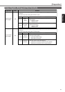
Application Code Function
Connector
pin No.
Strobe signal
input
STB
24
• When this is connected to COM– of the control signal power supply, the
servo driver starts the movement to the specified point.
• When 10ms or more has passed after setting specified point input, connect
the strobe signal input (STB) to COM–. It is possible that the servo driver is
unable to read specified point input properly.
• Input STB signal 10ms or longer. Also, reset STB signal to opened
condition after receiving BUSY signal from the servo driver in order to
ensure that STB signal is received reliably.
Multi-function
input 1
Multi-function
input 2
EX-IN1
EX-IN2
22
25
Function can be selected and set by Pr5A and 5C out of the options below.
Instantaneous stop, temporary stop, deceleration stop, high-speed normal
rotation jog, high-speed reverse rotation jog, and alarm clearing
Input logic can be set by SV.Pr59 and 5B.
Point No.
0 (00H)
1 (01H)
2 (02H)
3 (03H)
4 (04H)
5 (05H)
6 (06H)
7 (07H)
8 (08H)
9 (09H)
10 (0AH)
59 (3BH)
60 (3CH)
61 (3DH)
62 (3EH)
63 (3FH)
P32IN
H
H
H
H
H
H
H
H
H
H
H
L
L
L
L
L
P16IN
H
H
H
H
H
H
H
H
H
H
H
L
L
L
L
L
P8IN
H
H
H
H
H
H
H
H
L
L
L
L
L
L
L
L
P4IN
H
H
H
H
L
L
L
L
H
H
H
H
L
L
L
L
P2IN
H
H
L
L
H
H
L
L
H
H
L
L
H
H
L
L
P1IN
H
L
H
L
H
L
H
L
H
L
H
L
H
L
H
L
Description
Alarm clearing instruction
Moves to step parameter 1.
Moves to step parameter 2.
Moves to step parameter 3.
Moves to step parameter 4.
Moves to step parameter 5.
Moves to step parameter 6.
Moves to step parameter 7.
Moves to step parameter 8.
Moves to step parameter 9.
Moves to step parameter 10.
Moves to step parameter 59.
Moves to step parameter 60.
High-speed jog operation (negative)
High-speed jog operation (positive)
Homing instruction
•
•
•
•
•
•