


64
Parameter Setup
Standard default : < >
Servo
PrNo.
Setup
range
UnitTitle Function/Content
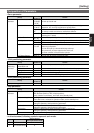
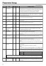
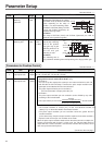
34
0 to 20000
<33>*
–1st control
switching
hysteresis
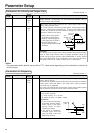
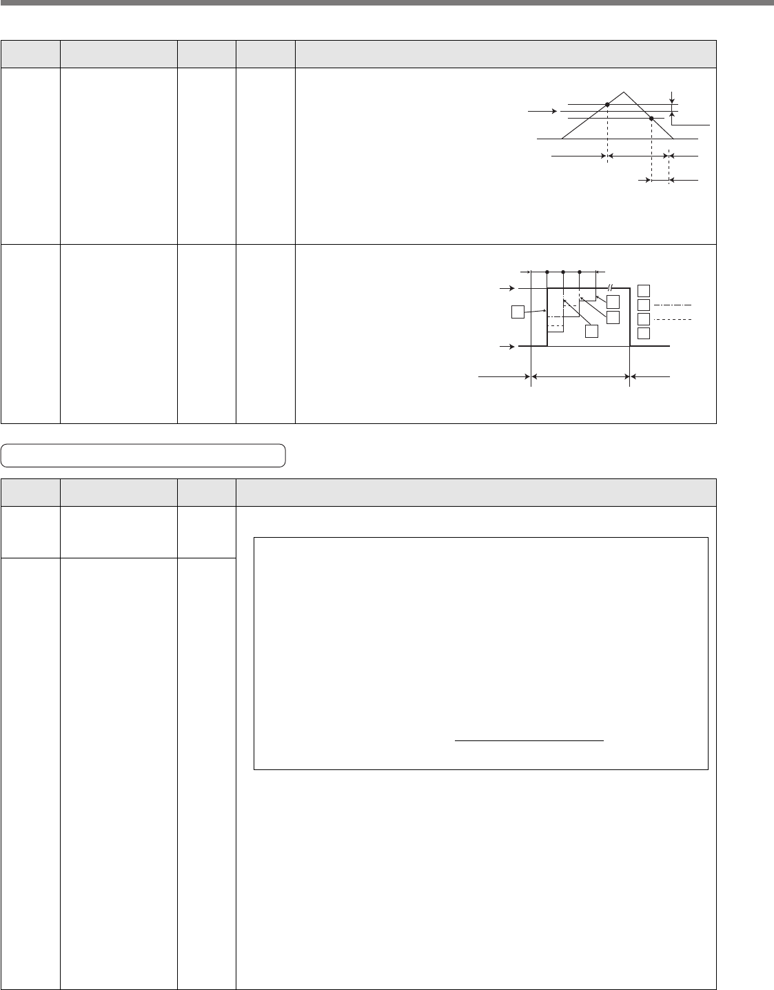
You can set up hysteresis width to be
implemented above/below the judging
level which is set up with SV.Pr33. Unit
varies depending on the setup of
SV.Pr31 (1st control switching mode).
Definitions of SV.Pr32 (Delay), SV.Pr33
(Level) and SV.Pr34 (Hysteresis) are
explained in the fig. below.
<Caution>
The setup of
SV.
Pr33 (Level) and
SV.
Pr34 (Hysteresis) are valid as
absolute values (positive/negative).
SV.Pr33
0
SV.Pr34
SV.Pr32
1st gain 2nd gain 1st gain
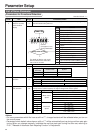
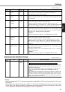
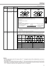
35
0 – 10000
<20>*
(setup
value +1)
x 166µs
Position loop gain
switching time
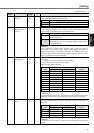
You can setup the
step-by-step switching
time to the position
loop gain only at gain
switching while the 1st
and the 2nd gain
switching is valid.
<Caution>
The switching time is
only valid when switching from small position gain to large position gain.
SV.
Pr35=
Kp1
(SV.Pr10)
166
166 166
166µs
Kp2
(SV.Pr18)
1st gain
e.g.)
2nd gain
bold line
thin line
1st gain
0
0
1
1
2
2
3
3
Kp1(SV.Pr10)>Kp2(SV.Pr18)
Parameters for Position Control
Servo
PrNo.
Setup
range
Title Function/Content
Standard default : < >
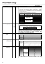
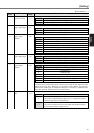
44
*
45
*
1 to 32767
<10000>
0 to 32767
<10000>
Numerator of
output pulse ratio
Denominator of
output pulse ratio
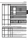
You can set up the pulse counts to be fed out from the pulse output (X5 0A+ : Pin-
21, 0A- : Pin-22, 0B+ : Pin-48, 0B- : Pin-49).
• In the case that the encoder pulse is output (When the control mode is
the position control mode and SV.Pr46 = 0, 1).
• SV.Pr45=0 :
You can set up the output pulse counts per one motor revolution for each OA
and OB with the SV.Pr44 setup. Therefore the pulse output resolution after
quadruple can be obtained from the formula below.
• SV.Pr45≠0 :
The pulse output resolution per one revolution can be divided by any ration
according to the formula below.
<Cautions>
• The encoder resolution is 131072 [P/r] for the 17-bit absolute encoder, and
10000 [P/r] for the 5-wire 2500P/r incremental encoder.
• The pulse output resolution per one revolution cannot be greater than the
encoder resolution.
(In the above setup, the pulse output resolution equals to the encoder resolution.)
• Z-phase is fed out once per one revolution of the motor.
When the pulse output resolution obtained from the above formula is multiple of 4,
Z-phase synchronizes with A-phase. In other case, the Z-phase width equals to
output with the encoder resolution, and becomes narrower than A-phase, hence
does not synchronize with A-phase.
(Continue to the next page.)
The pulse output resolution per one revolution =
SV.Pr44 (Numerator of output pulse ratio) X 4
SV.Pr44
(Numerator of output pulse ratio)
SV.Pr45
(Denominator of output pulse ratio)
Pulse output resolution per one revolution x Encoder resolution