


61
[Setting]
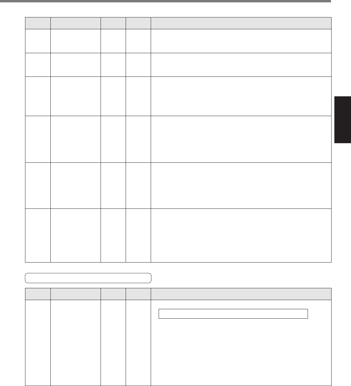
Setting
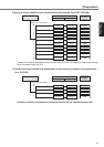
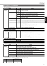
Parameters for Auto-Gain Tuning
Standard default : < >
Servo
PrNo.
Setup
range
UnitTitle Function/Content
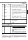
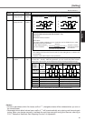
2E
–200 to 2000
<0>
0.1Hz2nd vibration
suppression filter
While you set up SV.Pr2D (2nd vibration suppression frequency), set this
up to smaller value when torque saturation occurs, and to larger value
when you need faster action.
Use with the setup of 0 in normal operation. Refer to P.161, "Damping
control" of Adjustment .
<Caution>
Setup is also limited by 10.0[Hz] – SV.Pr2D
<
=
SV.Pr2E
<<<
=
SV.Pr2D
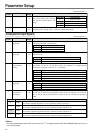
2B 0 to 2000
<0>
0.1Hz1st vibration
suppression
frequency
You can set up the 1st vibration suppression frequency of the damping
control which suppress vibration at the load edge.
The driver measures vibration at load edge. Setup unit is 0.1[Hz].
The setup frequency is 10.0 to 200.0[Hz]. Setup of 0 to 99 becomes invalid.
Refer to P.161, "Damping control" as well before using this parameter.
2C
–200 to 2000
<0>
0.1Hz1st vibration
suppression filter
While you set up SV.Pr2B (1st vibration suppression frequency), set this
up to smaller value when torque saturation occurs, and to larger value
when you need faster action.Use with the setup of 0 in normal operation.
Refer to P.161, "Damping control" of Adjustment .
<Caution>
Setup is also limited by 10.0[Hz] – SV.Pr2B
<
=
SV.Pr2C
<
=
SV.Pr2B
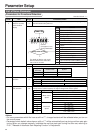
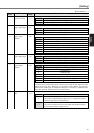
2D 0 to 2000
<0>
0.1Hz2nd vibration
suppression
frequency
You can set up the 2nd vibration suppression frequency of the damping
control which suppress vibration at the load edge.
The driver measures vibration at the load edge. Setup unit is 0.1 [Hz].
Setup frequency is 10.0 to 200.0 [Hz]. Setup of 0-99 becomes invalid.
Refer to P.161, "Damping control" of Adjustment as well before using this
parameter.
2A 0 to 99
<0>
–2nd notch depth
selection
You can set up the 2nd notch depth of the resonance suppressing filter.
Higher the setup, shallower the notch depth and smaller the phase delay
you can obtain.
29 0 to 4
<2>
–2nd notch width
selection
You can set up the notch width of 2nd resonance suppressing filter in 5
steps. Higher the setup, larger the notch width you can obtain.
Use with default setup in normal operation.
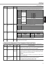
Standard default : < >
Servo
PrNo.
Setup
range
UnitTitle Function/Content
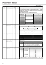
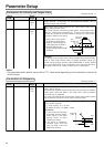
20
0 to 10000
<250>*
%Inertia ratio
You can set up the ratio of the load inertia against the rotor (of the motor) inertia.
When you execute the normal auto-gain tuning, the load inertial will be
automatically estimated after the preset action, and this result will be
reflected in this parameter.
The inertia ratio will be estimated at all time while the real-time auto-gain
tuning is valid, and its result will be saved to EEPROM every 30 min.
<Caution>
If the inertia ratio is correctly set, the setup unit of SV.Pr11 and SV.Pr19
becomes (Hz). When the inertia ratio of SV.Pr20 is larger than the actual,
the setup unit of the velocity loop gain becomes larger, and when the
inertia ratio of SV.Pr20 is smaller than the actual, the setup unit of the
velocity loop gain becomes smaller.
SV.Pr20 = (load inertia/rotor inertia) X 100 [%]
<Notes>
• Anything marked with “(P)” on the servo parameter number (Servo PrNo.) can be used only for the “posi-
tion control”.
• Parameters which default values have a suffix of "*" will be automatically set up during real time auto-gain
tuning. When you change manually, invalidate the real-time auto-gain tuning first then set, referring to
P.151, "Release of Automatic Gain Adjusting Function" of Adjustment.