


30
System Configuration and Wiring
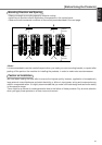
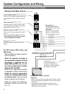
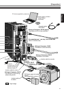
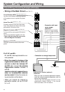
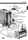
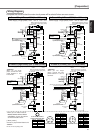
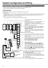
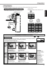
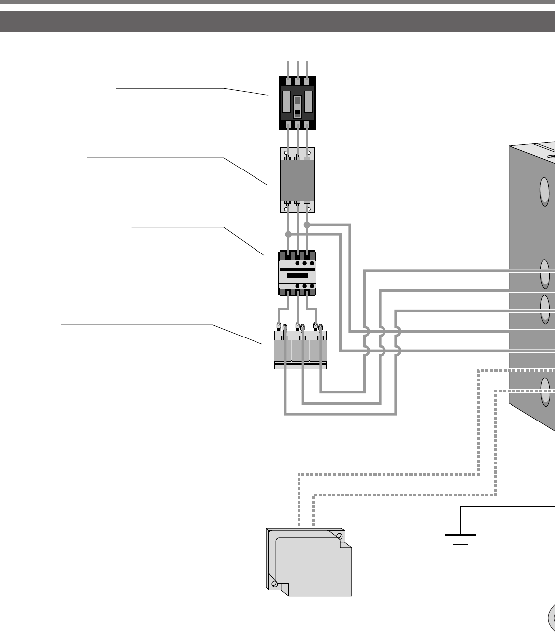
Overall Wiring (Connecting Example of E-frame)
Ground (earth)
• Connection with input
power supply
<Remarks>
Before turning the power
supply on, check whether
the input voltage is correct.
• Connection to external components
P
B2
L1
L2
L3
r
t
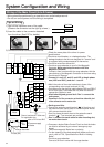
Pin P, B1 and B2...
B1 and B2 to be kept shorted for nor-
mal operation.
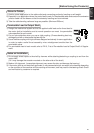
• When the capacity shortage of the
regenerative resister is found, dis-
connect a short bar between B1
and B2, then connect the external
regenerative resister between P
and B2.
Install an external regenerative re-
sister on incombustible material,
such as metal. Follow the same wir-
ing connection as the above.
• When you connect an external re-
generative resister, set up SV.Pr6C
to 1 or 2.
Regenerative resistor (optional)
<Remarks>
When you use an external regenerative resister,
install an external protective apparatus, such as
thermal fuse without fail.
Thermal fuse and thermostat are built in to the
regenerative resistor (Option). If the thermal
fuse is activated, it will not resume.
Circuit Breaker (NFB)
Use the circuit breaker matching capacity
of the power source to protect the power
lines.
Noise Filter (NF)
Prevents external noise from the power
lines. And reduces an effect of the noise
generated by the servo driver.
Magnetic Contactor (MC)
Turns on/off the main power of the servo
driver.
Use a surge absorber together with this.
• Never start nor stop the servo motor
with this Magnetic Contactor.
Reactor (L)
Reduces harmonic current of the main
power.
(see P.32, 33 and 177.)
(see P.177 , 178.)
(see P.32, 33.)
(see P.189.)
• Wiring of the Main Circuit
(see P.36, 37.)