


35
[Preparation]
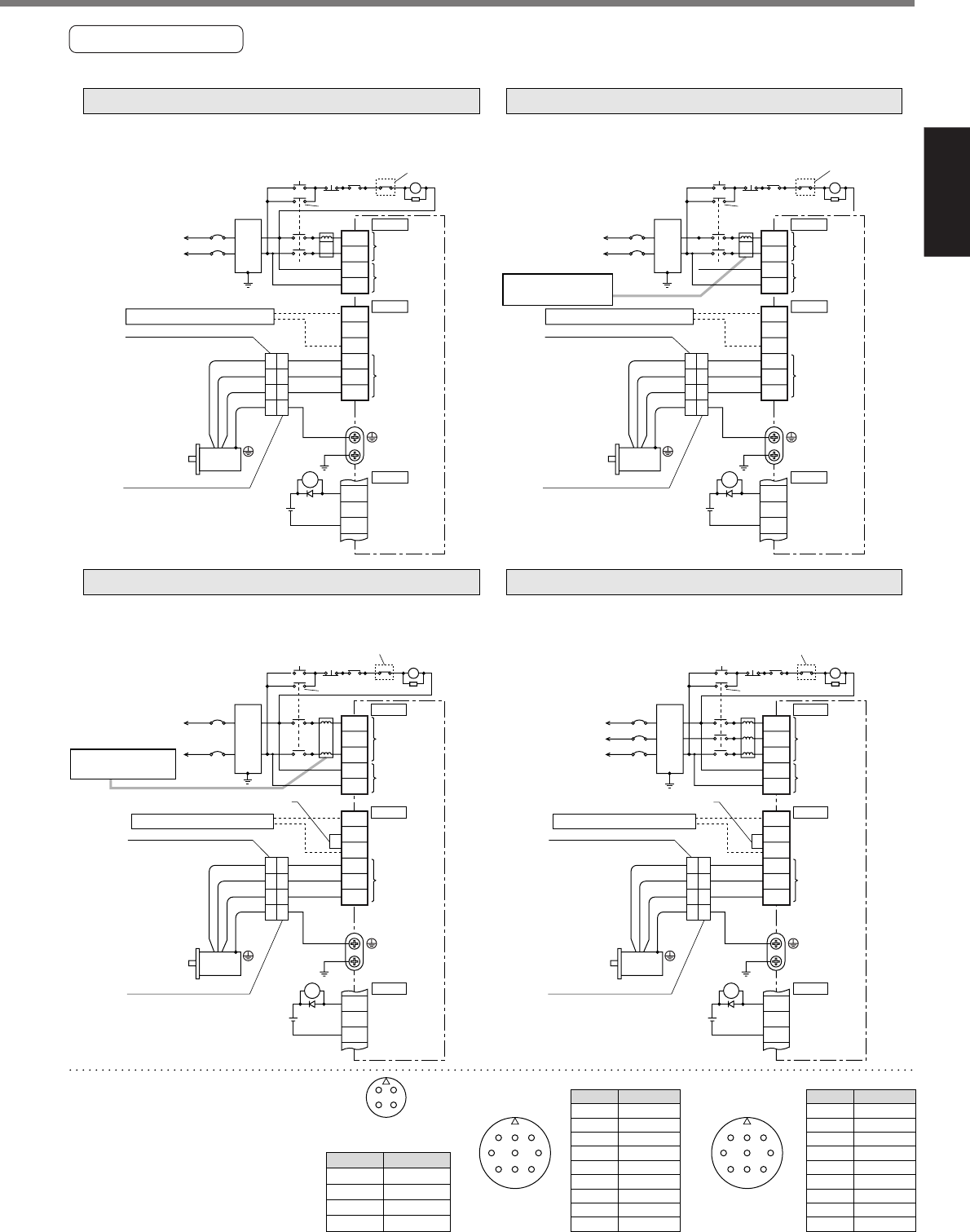
Preparation
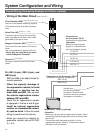
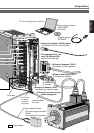
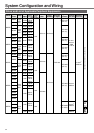
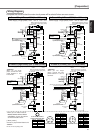
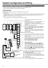
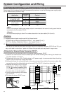
In Case of Single Phase, 100V (A and B-frame) In Case of Single Phase, 200V (A and B-frame)
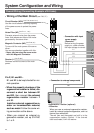
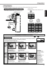
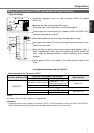
In Case of Single Phase, 200V (C and D-frame)
In Case of 3-Phase, 200V (C and D-frame)
A
B
D
C
AHG
CDE
BIF
CBA
IHG
FED
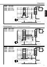
JL04V-2E20-4PE-B-R
JL04HV-2E22-22PE-B-R
JL04V-2E20-18PE-B-R JL04V-2E24-11PE-B-R
Power supply Single phase, 100V to 115V
+10%
–15%
+10%
–15%
Power supply Single phase, 200V to 240V
+10%
–15%
+10%
–15%
Noise
filter
Main power
supply
Control power
supply
Motor
ALM
15
ALM
L3
L1C
L2C
RB1
MC
NFB
RB3
RB2
U
V
W
L1
CN X2
Surge absorber
External regenerative resistor
COM–
17
DC12 to 24V
(±5%)
Red
White
Black
Green
1
2
3
4
1
2
3
4
Motor
connection
CN X5
CN X1
172167-1
Tyco Electronics AMP
172159-1
Tyco Electronics AMP
L
MC
ALMON OFF
Built-in thermostat of an external
regenerative resistor (light yellow)
MC
Noise
filter
Main power
supply
Control power
supply
Motor
ALM
L3
L1C
L2C
RB1
MC
NFB
RB3
RB2
U
V
W
L1
CN X2
External regenerative resistor
DC12 to 24V
(±5%)
Red
White
Black
Green
1
2
3
4
1
2
3
4
Motor
connection
CN X5
CN X1
172167-1
Tyco Electronics AMP
172159-1
Tyco Electronics AMP
L
MC
ALMON OFF
Use a reactor for
3-phase
Surge absorber
Built-in thermostat of an external
regenerative resistor (light yellow)
MC
15
ALM
COM–
17
PIN No.
Application
PIN No.
Application
External regenerative resistor
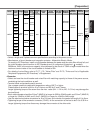
<Remarks>
When you use single
phase, connect the main
power between L1 and
L3 terminals.
Motor
L2
L3
L1C
L2C
RB1
MC
NFB
RB3
RB2
U
V
W
L1
1
2
3
4
1
2
3
4
(Remove the short wire when you connect
the external regenerative resistor.)
172167-1
Tyco Electronics AMP
172159-1
Tyco Electronics AMP
L
<Remarks>
When you use single
phase, connect the main
power between L1 and L3
terminals.
Motor
L2
L3
L1C
L2C
RB1
MC
NFB
RB3
RB2
U
V
W
L1
1
2
3
4
1
2
3
4
(Remove the short wire when you connect
the external regenerative resistor.)
*
172167-1
Tyco Electronics AMP
172159-1
Tyco Electronics AMP
L
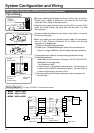
A U-phase
V-phase
W-phase
Ground
PIN No.
B
C
D
Application
G
H
A
F
I
B
E
D
C
Brake
Brake
NC
U-phase
V-phase
W-phase
Ground
Ground
NC
A Brake
Brake
NC
U-phase
V-phase
W-phase
Ground
Ground
NC
B
C
D
E
F
G
H
I
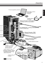
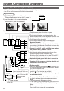
<Remark>
Do not connect anything to NC.
* When you use motor model of
MSMA, MDMA, MFMA, MHMA
and MGMA, use the connections
as the below table shows.
[Motor portion]
Connector : by Japan Aviation Electronics Ind.
CN X2
CN X1
ALM
DC12 to 24V
(±5%)
CN X5
CN X2
CN X1
CN X5
ALM
DC12 to 24V
(±5%)
MC
ALMON OFF
MC
ALMON OFF
Use a reactor for
3-phase
Noise
filter
Noise
filter
Main power
supply
Control power
supply
Motor
connection
Main power
supply
Control power
supply
Motor
connection
Power supply Single phase, 200V to 240V
+10%
–15%
+10%
–15%
Power supply 3-phase, 200V to 240V
+10%
–15%
+10%
–15%
Red
White
Black
Green
External regenerative resistor
Red
White
Black
Green
*
Surge absorber
Built-in thermostat of an external
regenerative resistor (light yellow)
MC
Surge absorber
Built-in thermostat of an external
regenerative resistor (light yellow)
MC
15
ALM
COM–
17
15
ALM
COM–
17
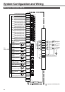
Wiring Diagram
Compose the circuit so that the main circuit power will be shut off when an error occurs.