


37
[Preparation]
Preparation
A
B
D
C
AHG
CDE
BIF
CBA
IHG
FED
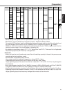
JL04V-2E20-4PE-B-R
JL04HV-2E22-22PE-B-R
JL04V-2E20-18PE-B-R JL04V-2E24-11PE-B-R
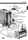
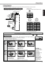
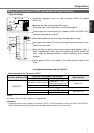
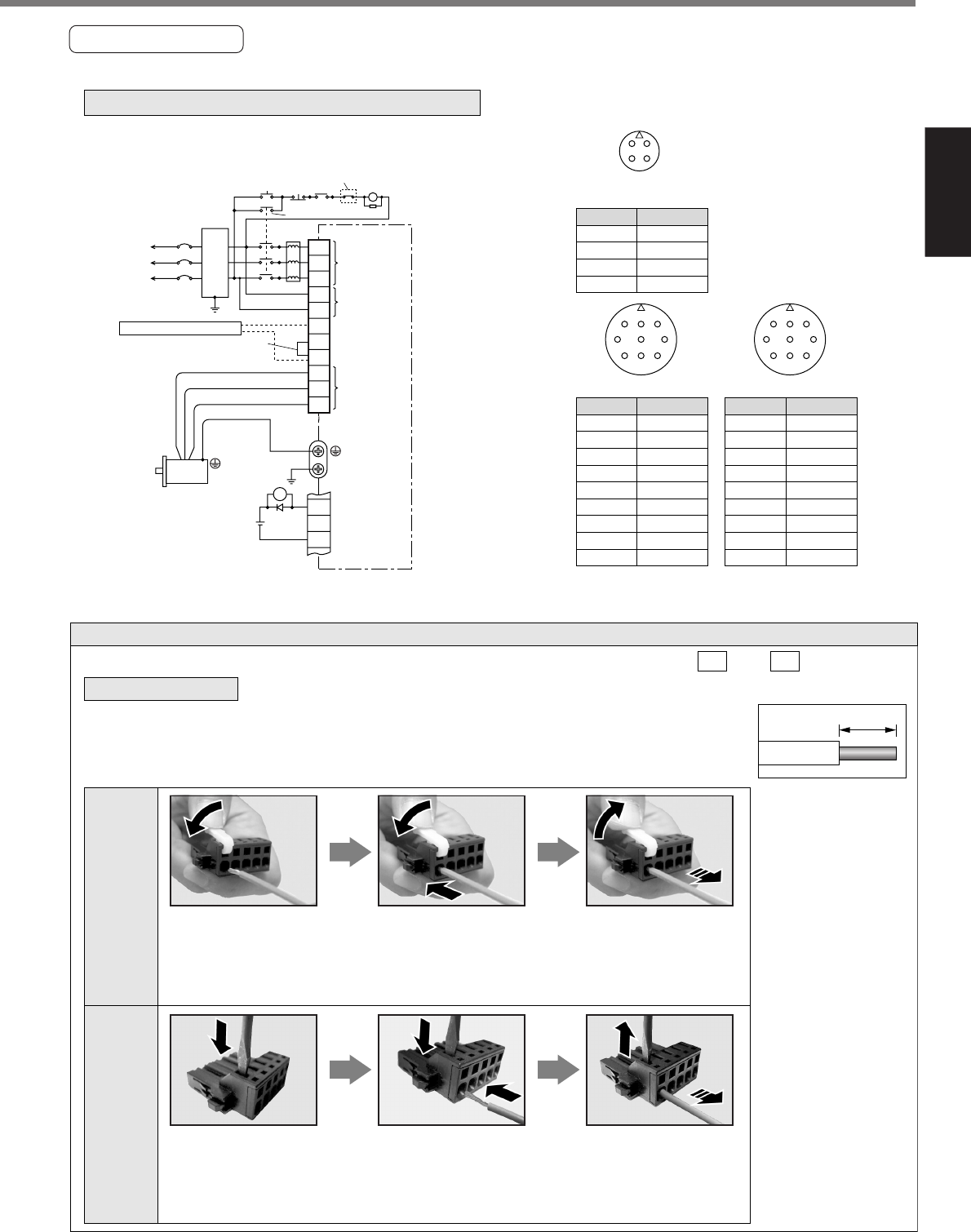
In Case of 3-Phase, 200V (E and F-frame)
PIN No. Application
PIN No. Application
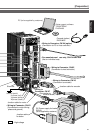
[Motor portion]
Connector : by Japan Aviation Electronics Ind.
A U-phase
V-phase
W-phase
Ground
PIN No.
B
C
D
Application
G
H
A
F
I
B
E
D
C
Brake
Brake
NC
U-phase
V-phase
W-phase
Ground
Ground
NC
A Brake
Brake
NC
U-phase
V-phase
W-phase
Ground
Ground
NC
B
C
D
E
F
G
H
I
<Remark>
Do not connect anything to NC.
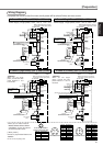
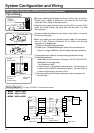
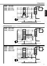
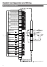
Power supply 3-phase, 200V to 230V
+10%
–15%
+10%
–15%
Red
White
Black
Green
Motor
15
ALM
L2
L3
r
t
P
MC
MC
NFB
ALM
ON
OFF
B1
B2
U
V
W
L1
COM–
DC12 to 24V
(±5%)
(Remove the short bar when you connect
the external regenerative resistor.)
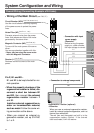
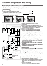
17
L
Noise
filter
Main power
supply
Control power
supply
Motor
connection
External regenerative resistor
Surge absorber
Built-in thermostat of an external
regenerative resistor (light yellow)
MC
ALM
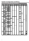
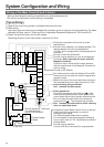
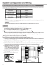
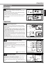
How to connect
Attach the handle lever
to the handling slot on
the upper portion.
Press down the lever to
push down the spring.
Insert the peeled cable
while pressing down the
lever, until it hits the
insertion slot (round
hole).
Release the lever.
• Follow the procedures below for the wiring connection to the Connector CN X1 and X2 .
1. Peel off the insulation cover of the cable. (see the right fig for exact length for peeling.)
2. Insert the cable to the connecter in the following 2 methods.
(a) Using the attached Handle Lever
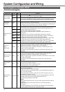
(b) Using a screw driver (blade width of 3.0 to 3.5 mm)
8 to 9mm
Wiring method to connector (A to D-frame)
Press the screw driver
to the handling slot on
the upper portion to
push down the spring.
Insert the peeled cable
while pressing down the
screw driver, until it hits
the insertion slot (round
hole).
Release the screw
driver.
* You can pull out the cable by pushing down the spring as the above.
* You can pull out the cable by pushing down the spring as the above.
<CAUTION>
•
Peel off the cable
with exact length (8
to 9 mm).
•
Take off the
connector from the
Servo Driver
before making
connection.
•
Insert one cable
into each one of
cable insertion slot.
•
Pay attention to
injury by screw
driver.
(a)
Using
handle
lever
(b)
Using
screw
driver
Wiring Diagram
Compose the circuit so that the main circuit power will be shut off when an error occurs.