Interfaces8–8
Interface Configuration Options 60–99
The final step in the printer/host computer interfacing procedure requires
obtaining a configuration printout (self–test 00.1) to ensure that the correct
interface control configuration options (addresses 60–99) are set. Addresses
60–66 apply to the parallel (Centronics and Dataproducts) interfaces. Refer
to Chapter 4 for reconfiguration procedures.
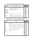
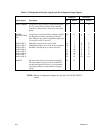
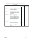
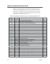
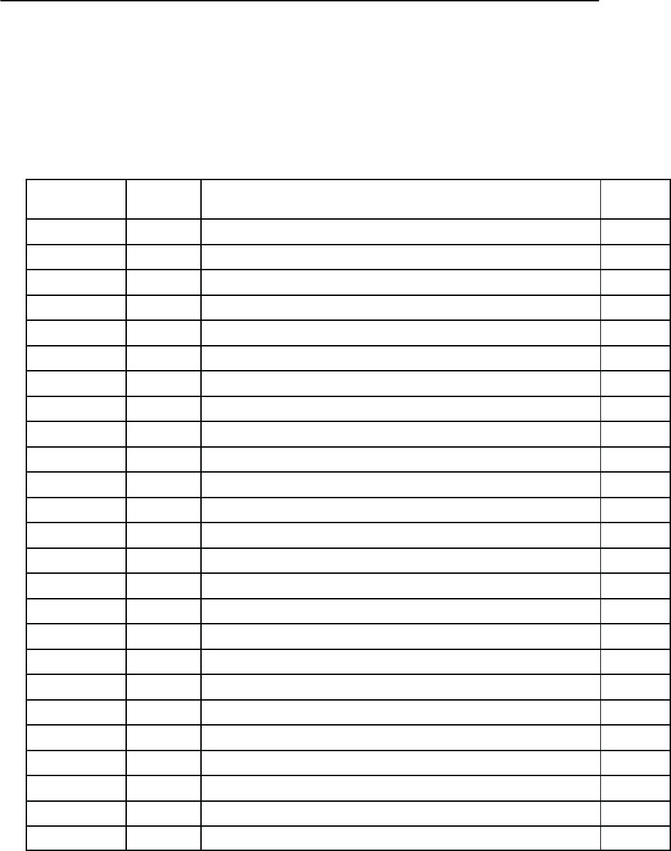
Table 8–5. Quick Reference Table for Interface Configuration Options 60 –99
Configuration
Number
Printer
T
ype
Configuration Option Page #
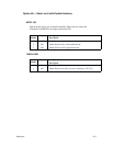
60 All Data Line 8 with Parallel Interface 8–9
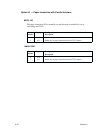
61 All Paper Instruction with Parallel Interface 8–10
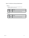
62 All Data Strobe Line Polarity with Parallel Interface 8–11
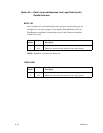
63 All Data Lines and Response Line Logic Polarity with Parallel Interface 8–12
64 All Reserved for Future Use
65 All Busy 8–13
66 All Parallel Interface Selection 8–14
67–69 All Reserved for Future Use
70 MVP/L150 Serial Interface/Protocol Selection 8–15
71 MVP/L150 Serial Data T
ransfer Baud Rate
8–16
72 MVP/L150
Data W
ord Interface Configuration 8–17
73 MVP/L150 Transmitted Data Polarity 8–18
74 MVP/L150
Request to Send (R
TS) 8–19
75 MVP/L150 Clear to Send (CTS) and Carrier Detect (CD) 8–20
76 MVP/L150 Data Set Ready (DSR–RS–232 pin 6) 8–21
77 MVP/L150
Reverse Channel (RC)
8–22
78 MVP/L150 Data Terminal Ready (DTR) 8–23
79 MVP/L150
XON Buf
fer Level Threshold 8–24
80 MVP/L150 XOFF Buffer Level Threshold 8–24
81 MVP/L150 Current Loop Out 8–24
82 MVP/L150 Protocol Character Assignment – XON or ACK 8–25
83 MVP/L150 Protocol Character Assignment – XOFF or NAK 8–25
84 MVP/L150 Protocol Character Assignment – ETX 8–25
85–89 All Reserved for Future Serial Interface Options
90–99 All Reserved for Future Options


