Rev.1.02 Jul 01, 2005 page 120 of 314
REJ09B0126-0102
M16C/6N Group (M16C/6NL, M16C/6NN) 13. Three-Phase Motor Control Timer Function
Under development
This document is under development and its contents are subject to change.
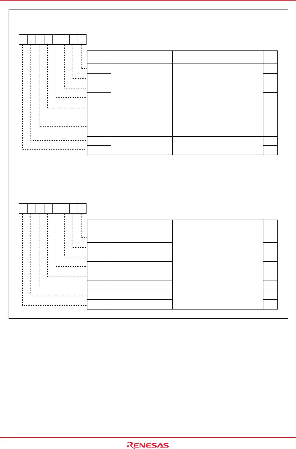
Figure 13.7 TRGSR Register and TRBSR Register
Trigger Select Register
Symbol Address After Reset
TRGSR 0383h 00h
b7 b6 b5 b4 b3 b2 b1 b0
RW
RW
RW
RW
RW
RW
RW
RW
RW
Bit Name
Bit
Symbol
TA1TGL
TA1TGH
TA2TGL
Timer A1 Event/Trigger
Select Bit
TA2TGH
TA3TGL
TA3TGH
TA4TGL
TA4TGH
Function
Set to "01b" (TB2 underflow) before
using a V-phase output control circuit
Timer A2 Event/Trigger
Select Bit
Set to "01b" (TB2 underflow) before
using a W-phase output control circuit
:
Selects an input to the TA3IN pin
(1)
: Selects TB2
(2)
: Selects TA2
(2)
: Selects TA4
(2)
Timer A3 Event/Trigger
Select Bit
Timer A4 Event/Trigger
Select Bit
Set to "01b" (TB2 underflow) before
using a U-phase output control circuit
NOTES:
1. Set the corresponding port direction bit to "0" (input mode).
2. Overflow or underflow.
b5
0
0
1
1
b4
0
1
0
1
Count Start Flag
Symbol Address After Reset
TABSR 0380h 00h
b7 b6 b5 b4 b3 b2 b1 b0
RW
RW
RW
RW
RW
RW
RW
RW
RW
Bit Name
Bit
Symbol
TA0S
TA1S
TA2S
TA3S
TA4S
TB0S
TB1S
TB2S
Function
0 : Stops counting
1 : Starts counting
Timer A0 Count Start Flag
Timer A1 Count Start Flag
Timer A2 Count Start Flag
Timer A3 Count Start Flag
Timer A4 Count Start Flag
Timer B0 Count Start Flag
Timer B1 Count Start Flag
Timer B2 Count Start Flag


