Rev.1.02 Jul 01, 2005 page 303 of 314
REJ09B0126-0102
M16C/6N Group (M16C/6NL, M16C/6NN) 22. Usage Precaution
Under development
This document is under development and its contents are subject to change.
22.13.4 CAN Transceiver in Boot Mode
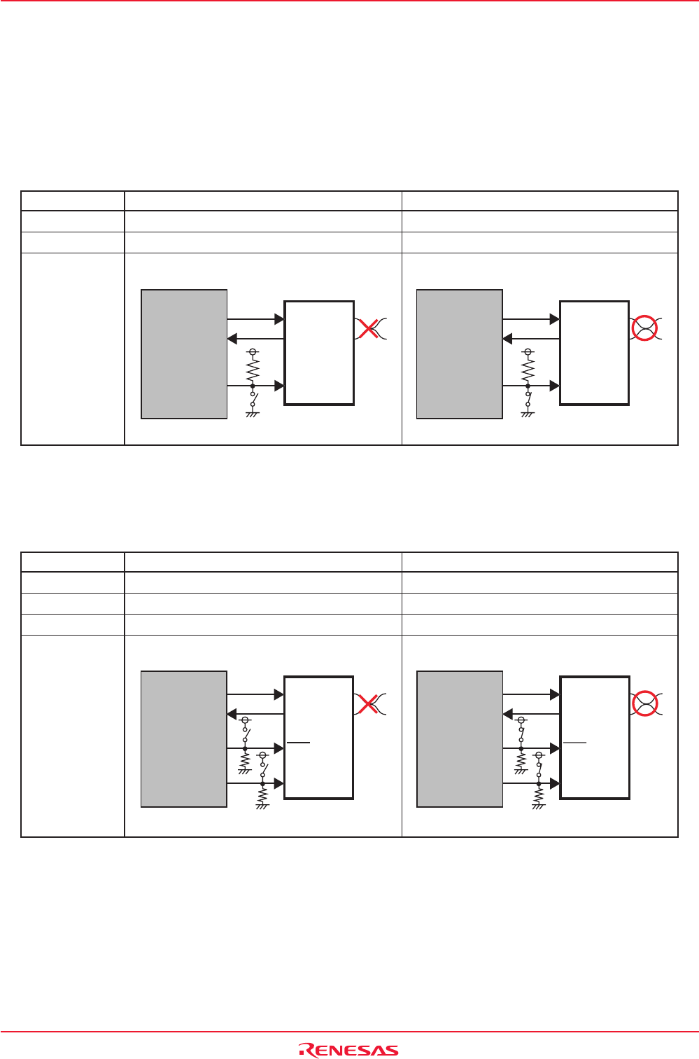
When programming the flash memory in boot mode via CAN bus, the operation mode of CAN transceiver
should be set to “high-speed mode” or “normal operation mode”. If the operation mode is controlled by
the microcomputer, CAN transceiver must be set the operation mode to “high-speed mode” or “normal
operation mode” before programming the flash memory by changing the switch etc. Tables 22.6 and 22.7
show pin connections of CAN transceiver.
Table 22.6 Pin Connections of CAN Transceiver (In case of PCA82C250: Philips product)
Standby Mode High-speed Mode
Rs Pin
(1)
“H”“L”
CAN Communication
impossible possible
Connection
NOTES:
1.The pin which controls the operation mode of CAN transceiver.
2.Connect to enabled port to control CAN transceiver.
Table 22.7 Pin Connections of CAN Transceiver (In case of PCA82C252: Philips product)
M16C/6NL, M16C/6NN
PCA82C250
CTX0
CRX0
Por
t
(2)
TXD
RXD
Rs
CANH
CANL
Switch OFF
M16C/6NL, M16C/6NN
PCA82C250
CTX0
CRX0
TXD
RXD
Rs
CANH
CANL
Port
(2)
Switch ON
Sleep Mode Normal Operation Mode
_______
STB Pin
(1)
“L”“H”
EN Pin
(1)
“L”“H”
CAN Communication
impossible possible
Connection
NOTES:
1. The pin which controls the operation mode of CAN transceiver.
2. Connect to enabled port to control CAN transceiver.
M16C/6NL, M16C/6NN
PCA82C252
CTX0
CRX0
TXD
RXD
STB
CANH
CANL
EN
Switch OFF
Por
t
(2)
Por
t
(2)
M16C/6NL, M16C/6NN
PCA82C252
CTX0
CRX0
TXD
RXD
STB
CANH
CANL
EN
Por
t
(2)
Por
t
(2)
Switch ON


