Rev.1.02 Jul 01, 2005 page 211 of 314
REJ09B0126-0102
M16C/6N Group (M16C/6NL, M16C/6NN) 18. CAN Module
Under development
This document is under development and its contents are subject to change.
18.5.2 CAN Operation Mode
The CAN operation mode is activated by setting the Reset bit in the C0CTLR register to “0”. If the Reset
bit is set to “0”, check that the State_Reset bit in the C0STR register is set to “0”.
If 11 consecutive recessive bits are detected after entering the CAN operation mode, the module initiates
the following functions:
• The module's communication functions are released and it becomes an active node on the network
and may transmit and receive CAN messages.
• Release the internal fault confinement logic including receive and transmit error counters. The module
may leave the CAN operation mode depending on the error counts.
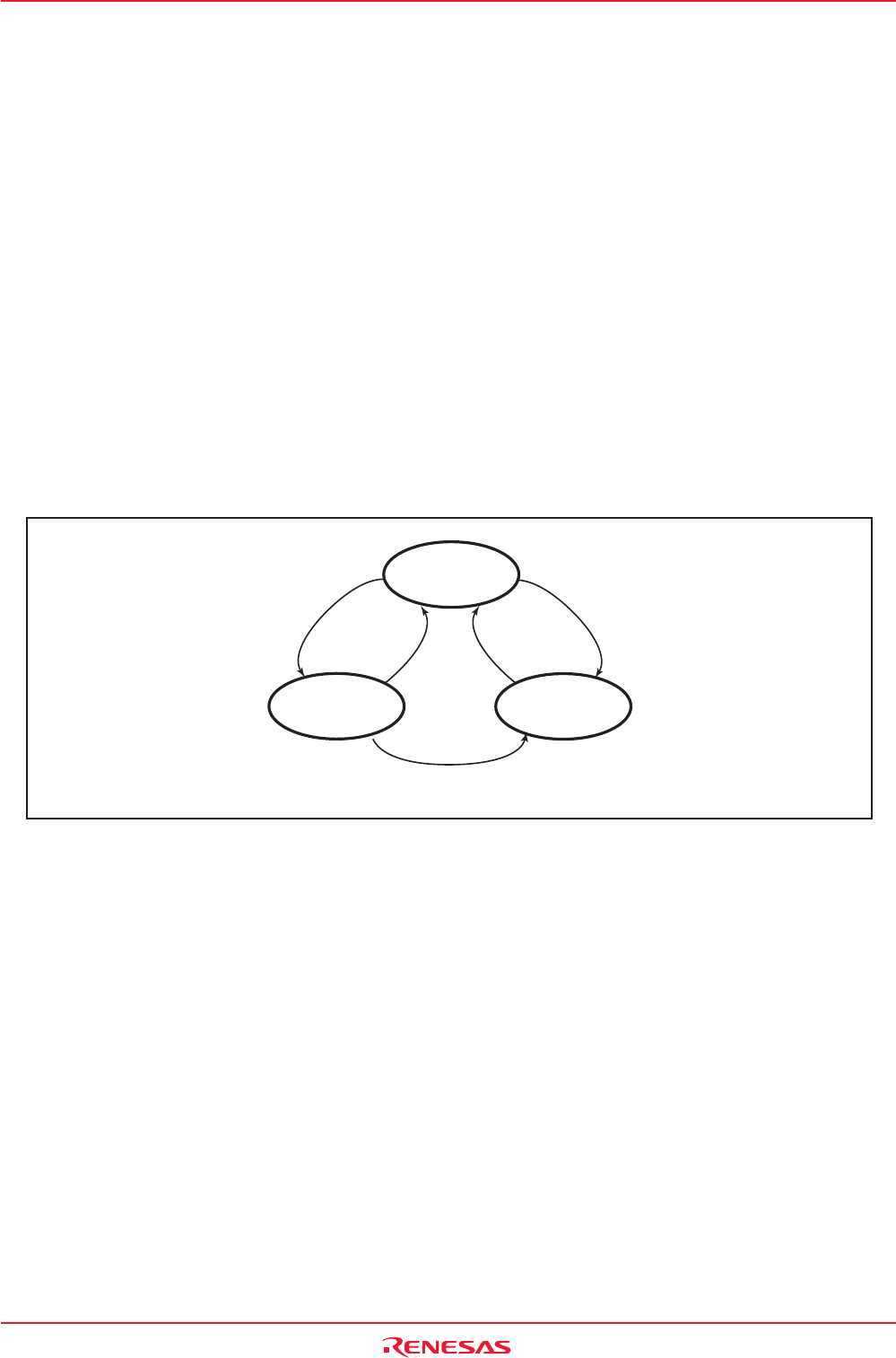
Within the CAN operation mode, the module may be in three different sub modes, depending on which
type of communication functions are performed:
• Module idle : The modules receive and transmit sections are inactive.
• Module receives : The module receives a CAN message sent by another node.
• Module transmits : The module transmits a CAN message. The module may receive its own message
simultaneously when the LoopBack bit in the C0CTLR register = 1 (Loop back mode
enabled).
Figure 18.14 shows sub modes of the CAN operation mode.
Figure 18.14 Sub Modes of CAN Operation Mode
18.5.3 CAN Sleep Mode
The CAN sleep mode is activated by setting the Sleep bit to “1” and the Reset bit to “0” in the C0CTLR
register. It should never be activated from the CAN operation mode but only via the CAN reset/initialization
mode.
Entering the CAN sleep mode instantly stops the clock supply to the module and thereby reduces power
dissipation.
18.5.4 CAN Interface Sleep Mode
The CAN interface sleep mode is activated by setting the CCLK3 bit in the CCLKR register to “1”. It
should never be activated but only via the CAN sleep mode.
Entering the CAN interface sleep mode instantly stops the clock supply to the CPU Interface in the module
and thereby reduces power dissipation.
Finish
reception
Module idle
TrmState = 0
RecState = 0
TrmState = 1
RecState = 0
Finish
transmission
Detect
an SOF
Start
transmission
Lost in arbitration
Module transmits
TrmState = 0
RecState = 1
Module receives
TrmState, RecState: Bits in C0STR register


