


Serial (RS-232) Controls and Operation
102 AX500 Motor Controller User’s Manual Version 1.9b. June 1, 2007
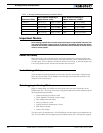
Connector I/O Pin Assignment (RS232 Mode)
When used in the RS232 mode, the pins on the controller’s DB15 connector are mapped
as described in the table below
TABLE 16. DB15 Connector pin assignment in RS232 mode
Pin
Number
Input or
Output Signal Description
1 and 9 Output Output C 100mA Accessory Output C
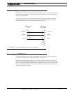
2 Output Data Out RS232 Data from Controller to PC
3 Input Data In RS232 Data In from PC
4 Input Input F Digital Input F readable RS232 mode
Dead man switch activation
5 and 13 Power Out Ground Controller ground (-)
6 Unused Unused Unused
7 Unused Unused Unused
8 Digital In and
Analog In
Input E / Ana in 4 Accessory input E
Dead man Switch Input
Activate Output C
Analog Input 4
10 Analog in Ana in 2 Channel 2 speed or position feedback input
11 Analog in Ana in 1 Channel 1 speed or position feedback input
12 Analog in Ana in 3 Analog input 3
14 Power Out +5V +5V Power Output (100mA max.)
15 Input Input EStop/Inv Emergency Stop or Invert Switch input
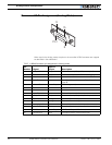
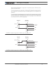
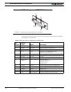
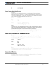
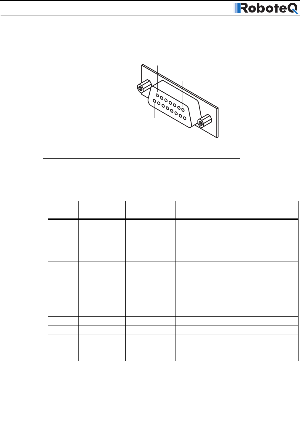
Pin1
8
15
9
FIGURE 1. Pin locations on the controller’s 15-pin connector